Converting old battery charger to bridge rectifier

Thread Starter

stryped

Joined Sep 17, 2023
136
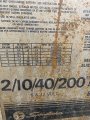
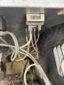
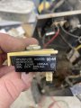
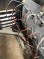
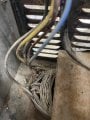
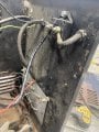
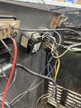
I have a 30• year old battery charger/ starter I would like to get working. The transformer has 8 metal lines coming out of it that plug into a steel plate that the positive charger cable attached to. I assume each pair are for the 4 different amperage settings of the charger. I assume I could use a bridge rectifier for each pair. However all of these steel lines have continuity with each other and they all put out vastly different ac voltages. How can I determine which to pair together for each bridge rectifier? Any help is appreciated!
 

Attachments

Tonyr1084

Joined Sep 24, 2015
9,744
A picture of the face might yield some useful information in solving your query.
That metal plate is a heat sink and stuffed with diodes. Does it work now? Or has it ceased to function?
As for finding very different AC voltages, are you measuring on the secondary side of the transformer? A transformer with multi-taps will have continuity between all wires and very low resistance. Report the voltages you're finding and make careful note of which sets of wires give you what results.
BE CAREFUL! You're very close to mains power, which is dangerous and could potentially be deadly. I'm sure you know that - but it's always worth saying rather than assuming one understands the danger.
 

Thread Starter

stryped

Joined Sep 17, 2023
136
A picture of the face might yield some useful information in solving your query.
That metal plate is a heat sink and stuffed with diodes. Does it work now? Or has it ceased to function?
As for finding very different AC voltages, are you measuring on the secondary side of the transformer? A transformer with multi-taps will have continuity between all wires and very low resistance. Report the voltages you're finding and make careful note of which sets of wires give you what results.
BE CAREFUL! You're very close to mains power, which is dangerous and could potentially be deadly. I'm sure you know that - but it's always worth saying rather than assuming one understands the danger.
Here is a picture of the front
 

Attachments

Tonyr1084

Joined Sep 24, 2015
9,744
I don't think that's a battery charger, I think it's a welder. I've seen those sorts of diodes in many welding machines but I've never seen them in a battery charger like those.

To turn it into a battery charger you need first to select a voltage range of about 14 volts. Maybe even 15 volts. Smart chargers are able to determine what the right charge voltage needs to be to prevent damaging the battery. If you turn that into a charger you're going to need a lot more control circuitry. Especially if you intend to charge batteries other than automotive types. Rechargeable batteries aren't just 'charged' up. Newer battery technology needs to be charged at a very specific profile.

My bet is that you'd probably be better off just buying the right kind of charger for the use. You CAN turn it into a charger, but you'll possibly damage a battery along the way. Or worse, miss the correct profile and you could have a fire or even an exploding battery. (Coarse language removed by moderator.)
 

MisterBill2

Joined Jan 23, 2018
27,285
I looked at those photos and that "steel plate with the wires attached" looks a whole lot like the heat sink for the silicon diode rectifiers soldered to it. And the "wires attached" look a lot like they have "faston" quarter inch lugs that match the tabs soldered to that heat sink. That makes it a whole lot different. The case may look a bit like an older generation shop welder, but that is not what it is.
Certainly we need to look at the panel and the full image of that plate with the table of capabilities on it. We need to be able to read all of the text. Likewise the controls panel.

AND A WARNING!!!!! before disconnecting any wires at all, make a drawing showing where each one connects. !!
I see NO METAL LINES in any of the pictures, but it may be metal dust on the wires. A GENTLE wiping may remove a lot and let the actual wire colors show.
The rectifiers appear to be soldered to that metal plate with all the wires going to it. THOSE are the rectifier diodes, they are easy to break and a pain to replace.

And for this project the TS will need to have a digital multimeter with both AC and DC voltage reading ability.
 

Thread Starter

stryped

Joined Sep 17, 2023
136
This is for sure a charger/starter. It was my dad’s and most likely purchased around 1990. There are 8 metal lines going from the transformer to that metal plate. I have since learned that those metal lines plug into a button diode that is soldered to the metal plate. I broke one of the diodes trying to remove one of the metal lines. It looks as if there is a thick cable coming from the transformer also that is the negative voltage for the system. I ordered a 200 amp full wave bridge rectifier.
Can I unplug all 8 metal lines from the steel plate and attach them to a terminal strip,!and connect the terminal strip to one of the ac inputs on the bridge rectifier? What would then go to the other ac input on the bridge rectifier, a connection to the negative wire coming out of the transformer mentioned earlier?
 

Thread Starter

stryped

Joined Sep 17, 2023
136
Also, I just checked the voltage of each of those 8 wires that plug into the plate. They all have 13.3 volts ac.
 

MisterBill2

Joined Jan 23, 2018
27,285
First, there is no such thing as a "half-wave bridge rectifier", since a single-phase bridge rectifier contains four diodes and a 3-phase bridge rectifier uses six diodes.
There does exist a "Half bridge" package that has two diodes in series, probably not suited for your application.
I hope that you recorded all of the connections prior to disconnecting the wires from the rectifiers and the switch.
The statement about " They all have 13.3 volts ac. " does not tell me relative to what point.
And we still have no hint as to the control panel markings, nor any hint about the many switch connections. It might be that the charger was functional as it was, I did not see any visible damage in the photos.
It may also be that the circuit was made for a full wave rectifier application.
 

Thread Starter

stryped

Joined Sep 17, 2023
136
If you simply disconnected all of the wires without recording where they went, the show may be over.
I took a picture so I do know where they are. The “control panel” has a selector switch with 1 terminal on top that has both the neutral wire from the blue as well as a black wire from somewhere. It also has 4 terminals on the bottom. These each have a different colored wire that goes to the transformer. The 13.3 volts was measuring each of the 8 metal lines that plug into the metal plate with a diode against a ground.
The original problem seemed to be low voltage while charging. I think it was the switch but the switch broke when checking as did a diode when unplugging one of the leads. I will attach more pictures. I really appreciate the help!
 

Attachments

Thread Starter

stryped

Joined Sep 17, 2023
136
I am not home but I’ll try to get. Picture of the control panel, however the picture with the writing on it I posted shows the different settings for voltge and montage level.
 

Tonyr1084

Joined Sep 24, 2015
9,744
There is also a timer beside the switch and a volt meter beside that.
Never heard of a welder with a timer on it. It MUST be a battery charger. However, I'm wondering how you get a 6V setting. The panel you DID take a picture of shows that it's 6V - 12V. If you're getting 13V on all lines (relative to what - like @MisterBill2 asks)?
 

Tonyr1084

Joined Sep 24, 2015
9,744
You probably have something like this. Based off the measurements you're stating it doesn't look like a good candidate for a battery charger. But I won't argue the point - what you have IS a battery charger. Below is a diagram of a transformer with a single primary and two separate secondaries. To better understand what you have you need to number the wires of the secondary and then record the values between each set of wires. You said you have 8 wires coming out of the transformer. Number them 1 through 8. Then list the voltages of lines
1 & 2
1 & 3
1 & 4
1 & 5
1 & 6
1 & 7
1 & 8
Then
2 & 3
2 & 4
2 & 5
2 & 6
2 & 7
2 & 8
Then
3 & 4
etc. till you have all the values. Then we can begin to build a clear picture of what you have. Simply telling us you have 13.3 VAC on all the wires, that's relative to what? We don't know. We can't tell how the transformer is wired. It's possible that four of the wires are intended for 6V AC output and the other four are also intended for 6V AC output. Put them in series and you get 12V AC. Put them in parallel (like the drawing) and you get 6V AC. Then rectify everything.

For a battery charger all you need is an AC voltage and a single diode. It will be slower than a full wave rectifier, but at the bare minimum, that's all you need.
OK, here's the drawing:
Screenshot 2024-11-27 at 11.31.38 AM.png
To be honest, the voltage you report doesn't make sense from a charger standpoint.
I still think you'd be better served with a new charger. Something like this or this. The second is a charger / starter. I own the first one. Use it to keep a float charge on a set of batteries used for a hoist.
 

Tonyr1084

Joined Sep 24, 2015
9,744
he 13.3 volts was measuring each of the 8 metal lines that plug into the metal plate with a diode against a ground.
Oh - the "ground" is not a ground. It is likely the positive line. And each line that you measure for voltage should be measured with nothing connected to the wire. Again, be careful. There's live mains in that box. Don't hurt yourself. We'd miss you. Unplug the machine before disconnecting anything. Then very carefully connect to the lines, and make sure nothing is shorted to anything else. Otherwise you're going to have some excitement. The kind you don't want.
 

Thread Starter

stryped

Joined Sep 17, 2023
136
You probably have something like this. Based off the measurements you're stating it doesn't look like a good candidate for a battery charger. But I won't argue the point - what you have IS a battery charger. Below is a diagram of a transformer with a single primary and two separate secondaries. To better understand what you have you need to number the wires of the secondary and then record the values between each set of wires. You said you have 8 wires coming out of the transformer. Number them 1 through 8. Then list the voltages of lines
1 & 2
1 & 3
1 & 4
1 & 5
1 & 6
1 & 7
1 & 8
Then
2 & 3
2 & 4
2 & 5
2 & 6
2 & 7
2 & 8
Then
3 & 4
etc. till you have all the values. Then we can begin to build a clear picture of what you have. Simply telling us you have 13.3 VAC on all the wires, that's relative to what? We don't know. We can't tell how the transformer is wired. It's possible that four of the wires are intended for 6V AC output and the other four are also intended for 6V AC output. Put them in series and you get 12V AC. Put them in parallel (like the drawing) and you get 6V AC. Then rectify everything.

For a battery charger all you need is an AC voltage and a single diode. It will be slower than a full wave rectifier, but at the bare minimum, that's all you need.
OK, here's the drawing:
View attachment 336801
To be honest, the voltage you report doesn't make sense from a charger standpoint.
I still think you'd be better served with a new charger. Something like this or this. The second is a charger / starter. I own the first one. Use it to keep a float charge on a set of batteries used for a hoist.
When measuring these wires, do they need to be unplugged from the button diodes? Does the switch that chooses the different amperage’s for charging need to be disconnected?
 

Tonyr1084

Joined Sep 24, 2015
9,744
You should be reading the voltage on the wires without being connected to anything. Otherwise you don't know how the other components are affecting your reading. Imagine my drawing without the rectifiers. You have the transformer primary and two secondaries. The secondaries should have nothing connected to them. Then carefully - will say it again CAREFULLY measure the voltages. And be sure nothing shorts out and nothing can bite you. I've been bitten many times measuring transformer voltages. It's not pleasant. It's even potentially harmful or worst, deadly. So be careful careful careful.
 

LesJones

Joined Jan 8, 2017
4,511
One thing that needs to be considdered is that the selector switch MAY select taappings on the primary to make adjustments to the secondary voltages. I think a schematic of how the charger is in it's original form needs to be traced out to understand how it was designed to work. From the pictures it is not clear how many diodes are mounted on the metal plate. (Heat sink.)

Les.
 

Thread Starter

stryped

Joined Sep 17, 2023
136
You should be reading the voltage on the wires without being connected to anything. Otherwise you don't know how the other components are affecting your reading. Imagine my drawing without the rectifiers. You have the transformer primary and two secondaries. The secondaries should have nothing connected to them. Then carefully - will say it again CAREFULLY measure the voltages. And be sure nothing shorts out and nothing can bite you. I've been bitten many times measuring transformer voltages. It's not pleasant. It's even potentially harmful or worst, deadly. So be careful careful careful.
Ok. So I should disconnect the amperage selection switch too? Won’t that cause zero voltage on the wires?
 
Top