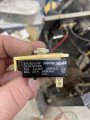
I was talking about the orientation of the diode, not the spade.First, it doesn't matter which orientation of the spade lug (the tab) is facing. Diodes conduct current in one direction and block it in the opposite.
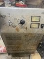
I can’t. Two of the diodes broke when taking the wires off.This is why I always say "Fully diagnose the problem before beginning repairs." If you can - put it back together and get it on a known good battery and see if the charge is going up. Watch the voltage AND watch the amperage. A nearly fully charged battery will only draw a few amps. A weak battery will draw much more current. A bad battery may never draw any amps no matter what.
Put it back together if you can. Then test it. KNOW what you're doing before you start.
Those colored wires go from the amperage selector switch to the transformer. A white wire and a black wire go together to the input of the switch and the colored wires are the output. Not all the button diodes on the plate have the same orientation. Some are upside down and some are righ side upFrom the odd bits of information that you have provided I think the windings have a center tap which is the negative output. All 8 diodes will have the cathode end connected to the heat sink. If you find pairs of windings with the same voltage reading with respect to the negative output and then measure the voltage between those two points then you will get a reading equal to twice the reading of each winding end and the negative output. ( These winding ends are the wires that go from the transformer to the anode ends of the diodes.)
The spread sheet in post #25 is usless as you have not identified the wire ends in the left hand columns on the pictures. also for 3 of the 4 sections with the comment black, blue or yellow wires connected. You don't say where thes wires come from and what they are connected to.
Les.
Thanks for the help what pictures or information do I need to provide to get an idea of how to get this to operate correctly with a bridge rectifier?I have been following this discussion with some interest. The information provided is in many small comments and pictures with very little to information that can tie them together into an overall picture. It is like looking at the pieces of a complex jigsaw puzzle.
I realize that the TS has limited electronic knowledge but that should not stop us from helping him in a very positive way. Before we make anymore assumptions and suggestions, I think a block diagram would be very helpful if it showed each component as a block, with the color coded wires shown connecting the blocks together. The normal convention would be power input on the left and charging output on the right.

Put it back together if you can.
Well, now you have no choice. Full wave rectification is not necessary for a battery charger. But you're going to need high amperage diodes that can be mounted to a heatsink.I can’t. Two of the diodes broke when taking the wires off.
I am attaching a picture as to why I was questioning it. The orientation the diodes are soldered to the metal are different. I am not sure on these diodes which end is cathode and which is a node, but their orientation appears different.I do not agree that the diodes may not be all the same polarity. They all MUST have the cathode end connected to the heat sink.
There are 4 wires to the switch: red, blue, black, and yellow. (The black may actually be brown it’s hard to tell. There is a white and black wire combined on the same spade terminal that I assume is the input of the switch. I am attaching a picture of the front and back of the switch area. The front picture is with the switch removed. I also will attach a picture of the switch with spec numbers on its side.The TS has NOT posted any pictures of the switch either from the front or the back. I don't understand why only three wires (Black, blue and yellow) shown connected to taps on the transformer primary. (It needs 4 for the 4 voltage tables.)
What about using a 200 amp bridge rectifier? I ordered one that should be here today. Or are you saying it would be better just solder 2 new diodes to replace the ones that broke?Well, now you have no choice. Full wave rectification is not necessary for a battery charger. But you're going to need high amperage diodes that can be mounted to a heatsink.
Thanks so much for the help! I did look up the number, but could not find anything on it. How would I connect the 4 bridge rectifiers?The third picture is what I thought was a solid state relay. So maybe the contacts on the time switch do handle the full mains current. To emulate the existing rectification system you would need to use 4 bridge rectifiers but you would only be using half of the diodes in each bridge. (These 4 bridge recifiers would only need to be rated a 50 amps each.) To use a single 200 amp bridge you would have to parallel all 4 centre tapped secondary windings. I would NOT advise doing this as the windings may not be wll enoug matched to share the load. (If you do try this you will have to make sure the ends of the windings that you connect togeter are in phase wit each other.) Have you looked up the specification of the existing diodes. (This may be dificult as they are so old.)
You can identify the anode and cathode of the diodes using your meter set to the diode test range.
Les.
Checking each of the 8 wires compared to the heavy black ground wire, each has 7.6 volts ac. Interestingly, when I attach the negative lead to that ground and do not connect the positive lead of the volt meter I get 3.6 volts roughlyThose are with the yellow wire attached to the switch.So I suggest, now that the end to end voltage is measured, to check the voltages relative to that heavy black wire.
You should also check the diameter of the wires used for the coils on the transformer itself. This will tell you (and us) something about the current ratings of each wire. You have to get to the transformer terminals to see the diameter of the actual transformer wires, not the wires coming off of the transformer, unless they are the same enamel coated type wire.Checking each of the 8 wires compared to the heavy black ground wire, each has 7.6 volts ac. Interestingly, when I attach the negative lead to that ground and do not connect the positive lead of the volt meter I get 3.6 volts roughlyThose are with the yellow wire attached to the switch.
With the red wire connected have 13.2 volts ac.
Withe the blue wire connected at the switch, all 8 wires have 9.8 v ac.
With the brown/ black wire connected, all 8 wires have 10.7
That picture looks to me like a push-button reset-able circuit breaker, rated at 25 amps. A closer examination should reveal the number of connections. An SSR will have four connections, a circuit breaker only needs two connections.Thanks so much for the help! I did look up the number, but could not find anything on it. How would I connect the 4 bridge rectifiers?
How would you insure the phase of the windings are the same if using a single bridge rectifier?
Which wires would you attach to each side of the bridge rectifier?That picture looks to me like a push-button reset-able circuit breaker, rated at 25 amps. A closer examination should reveal the number of connections. An SSR will have four connections, a circuit breaker only needs two connections.
Those diodes look a lot like the ones marketed by Motorola for use in Mopar alternators about 35 years ago. With pigtail leads they were rated about 15 amps, soldered to a heat sink with forced-air cooling they were good for 60+ amps. But I recently soldered to some of them and THAT WAS A PAIN, so I recommend stud mounted diodes with an adequate heat sink and a small fan/blower.
I have used a part of a bridge rectifier as a full-wave, NOT BRIDGE rectifier in a much smaller battery charger and it has performed well for over 20 years of fairly hard use. The scheme is the two ends of the transformer connect to the two AC terminals of the bridge, and the positive output comes from the "+" terminal. The "-" terminal is left open. The negative output connection is from the center tap of the transformer.
Rather than the expense of four bridge rectifiers, eight stud mount rectifiers attached to a heavy aluminum, brass, or copper plate as a heat sink might cost less, and be simpler to wire.
As for the enameled wires from the transformer, they are most certainly the same wire as the actual winding. The wires are brought out like that because it is cheaper than attaching it to a more flexible wire.
The diode manufacturers have some rather detailed instructions about correctly mounting stud-mount diodes to a heat sink, and certainly doing it correctly makes a great difference, and is the only way to achieve meeting the ratings.