Converting old battery charger to bridge rectifier

LesJones

Joined Jan 8, 2017
4,509
I agree with MisterBill2's comments in post #59. I would also recommend using stud mounted diodes as opposed to trying to use two of the diodes in a bridge rectifier. I did not find many stud mounted looking at Farnell, RS, Digi-key and Mouser websites.
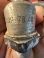
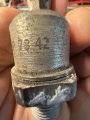
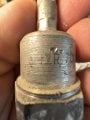
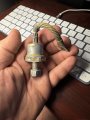
Forget the SSR theory. When I looked at the last picture in post #11 I thought it looked like an SSR. Today I googled the part number of that item and found out it was this 6 way rotary switch. which is a later version of the switch in the charger.

Les.
 

KeithWalker

Joined Jul 10, 2017
3,608
By the way, the diodes all have the positive on the blade terminals that plug into the 8 transformer wires and the negative on the plate. They measured ,40 to .48 with my diode tester.
I assume that you mean that those readings were made with the positive lead of the meter on the blade terminals. That means that the transformer wires are connected to rectifier anodes and the cathodes are connected to the plate. That will make the plate positive with respect to the common output.


Which wires would you attach to each side of the bridge rectifier?
Based on the information you have provided, we can only make wild guesses at this point. You will have to make some careful measurements to find out what the configuration of the transformer is. Label all the wires that are connected to the diodes, and make a corresponding label on the plate by each diode. Then disconnect all of the wires from the diodes.
With the power disconnected, using your resistance meter, carefully measure and note the resistance between each wire and every other wire, and the common thick wire from the transformer, as you started to do before. It the meter reads open circuit, mark it with a dash, rather than a zero (which indicates a short circuit). Also check for continuity between those wires and the wires connected to the selector switch, to find out if they are on a separate winding.
From those measurements you should be able to determine what the configuration of the secondary windings is.
Until you have done that, anything we suggest is guesswork based on unverified assumptions.
 

MisterBill2

Joined Jan 23, 2018
27,637
OK, it was not an image of some part of the charger we are discussing. My guess is that one is a much larger floor standing package arrangement that I have not had to be involved with. I HAVE considered the possibility of rewinding a 1100 watt MWO transformer to create a higher current capability 12 to 15 volt supply. My concern that has delayed that project is about the ability of those transformers to handle much power for a 100% duty cycle, when normally they only run for a few minutes at a time. Would heating of the primary be a serious problem??
 

Thread Starter

stryped

Joined Sep 17, 2023
136
I assume that you mean that those readings were made with the positive lead of the meter on the blade terminals. That means that the transformer wires are connected to rectifier anodes and the cathodes are connected to the plate. That will make the plate positive with respect to the common output.


Based on the information you have provided, we can only make wild guesses at this point. You will have to make some careful measurements to find out what the configuration of the transformer is. Label all the wires that are connected to the diodes, and make a corresponding label on the plate by each diode. Then disconnect all of the wires from the diodes.
With the power disconnected, using your resistance meter, carefully measure and note the resistance between each wire and every other wire, and the common thick wire from the transformer, as you started to do before. It the meter reads open circuit, mark it with a dash, rather than a zero (which indicates a short circuit). Also check for continuity between those wires and the wires connected to the selector switch, to find out if they are on a separate winding.
From those measurements you should be able to determine what the configuration of the secondary windings is.
Until you have done that, anything we suggest is guesswork based on unverified assumptions.
All of the 8 metal wires have continuity with each other. They also all have continuity with the negative cable going to the transformer.
They also all metal lines do not have any continuity with the wires that go from the transformer to the selection switch.
 

MisterBill2

Joined Jan 23, 2018
27,637
Those "Metal Lines" are enameled copper wire, which is reasonable insulation, but not very durable. That is to say it is easy to scratch off and have bare copper wire. What can work fairly well is feeding stud mount diodes that can be attached to a heat sink. Then one wire to each diode,similar to what was, but with new diodes. With an actual heat sink and a small fan it could be a much more compact package. And a nice battery charger system, with both VOLT and AMP meters.
How big is that transformer?? Physically, that is??
 

KeithWalker

Joined Jul 10, 2017
3,608
All of the 8 metal wires have continuity with each other. They also all have continuity with the negative cable going to the transformer.
They also all metal lines do not have any continuity with the wires that go from the transformer to the selection switch.
Then we can safely assume that the transformer has eight secondary windings with one end of each winding connected to the thick common negative wire. That was done to make it possible to drive the eight rectifiers in parallel. Presumably a single rectifier was not available at that time to handle the high current of the charger. Winding eight secondaries in parallel was also much easier than making a single winding of much thicker wire.

To make the charger into a power supply you must do several things. First, disconnect the transformer secondary common wire from everything else, and make sure that it is not connected internally to the transformer frame. Then connect it to one of the AC terminals of the 200A bridge rectifier. Connect all the other eight secondary wires to the other AC terminal on the bridge rectifier, keeping the wire lengths approximately the same as each other. You will then have fully rectified (un-smoothed) DC supply output between the + and - terminals of the bridge. The negative output should be connected to wherever the thick transformer secondary black common wire was previously connected. The positive output should be connected to where the red rectifier plate wire was previously connected.

Be aware that the output will then be full wave rectified so it will be a higher average voltage than before.
 
Last edited:

Thread Starter

stryped

Joined Sep 17, 2023
136
Then we can safely assume that the transformer has eight secondary windings with one end of each winding connected to the thick common negative wire. That was done to make it possible to drive the eight rectifiers in parallel. Presumably a single rectifier was not available at that time to handle the high current of the charger. Winding eight secondaries in parallel was also much easier than making a single winding of much thicker wire.

To make the charger into a power supply you must do several things. First, disconnect the transformer secondary common wire from everything else, and make sure that it is not connected internally to the transformer frame. Then connect it to one of the AC terminals of the 200A bridge rectifier. Connect all the other eight secondary wires to the other AC terminal on the bridge rectifier, keeping the wire lengths approximately the same as each other. You will then have fully rectified (un-smoothed) DC supply output between the + and - terminals of the bridge. The negative output should be connected to wherever the thick transformer secondary black common wire was previously connected. The positive output should be connected to where the red rectifier plate wire was previously connected.

Be aware that the output will then be full wave rectified so it will be a higher average voltage than before.
I am not wanting to turn it into a power supply, I want to make it continue to work as a charger. My thinking was taking the 4 terminals with zero voltage described earlier, connecting them to one of the ac terminals on the bridge rectifier, and taking the 4 that change voltage with the amp selector switch to the other c terminal. However you are saying connect all 8 to one ac terminal and the ground coming out of the transformer to the other? Will my charging voltages be correct?
By the way, the resistance of the 8 wires to each other as well as to the negative cable of the transformer were all .5.
Thanks again for the help!
 

KeithWalker

Joined Jul 10, 2017
3,608
I am not wanting to turn it into a power supply, I want to make it continue to work as a charger. My thinking was taking the 4 terminals with zero voltage described earlier, connecting them to one of the ac terminals on the bridge rectifier, and taking the 4 that change voltage with the amp selector switch to the other c terminal. However you are saying connect all 8 to one ac terminal and the ground coming out of the transformer to the other? Will my charging voltages be correct?
By the way, the resistance of the 8 wires to each other as well as to the negative cable of the transformer were all .5.
Thanks again for the help!
If you want it to work as a 200A half wave rectified battery charger with the same voltages as before, you will need one 200A or two 100A stud rectifiers, having the stud as the cathode.
If you have a 200A rectifier, drill a hole in the middle of your rectifier plate and bolt the rectifier to it, using heat sink compound. Connect all eight wires to the anode of the rectifier.
If you have two 100A rectifiers, bolt them onto the plate and connect any four of the wires to each anode.
It will then work the same as it did before, outputting the same voltages.
 

MrAl

Joined Jun 17, 2014
13,716
If you want it to work as a 200A half wave rectified battery charger with the same voltages as before, you will need one 200A or two 100A stud rectifiers, having the stud as the cathode.
If you have a 200A rectifier, drill a hole in the middle of your rectifier plate and bolt the rectifier to it, using heat sink compound. Connect all eight wires to the anode of the rectifier.
If you have two 100A rectifiers, bolt them onto the plate and connect any four of the wires to each anode.
It will then work the same as it did before, outputting the same voltages.
Did he measure the all the voltages and say they were the same for each and every winding?
 

Thread Starter

stryped

Joined Sep 17, 2023
136
If you want it to work as a 200A half wave rectified battery charger with the same voltages as before, you will need one 200A or two 100A stud rectifiers, having the stud as the cathode.
If you have a 200A rectifier, drill a hole in the middle of your rectifier plate and bolt the rectifier to it, using heat sink compound. Connect all eight wires to the anode of the rectifier.
If you have two 100A rectifiers, bolt them onto the plate and connect any four of the wires to each anode.
It will then work the same as it did before, outputting the same voltages.
So a bridge rectifier can’t be used for a battery charger
 

LesJones

Joined Jan 8, 2017
4,509
Keith, You seem to be assuming that the common point is the start of all 8 windings so all 8 wired to the rectifiers are in phase.
Mine an MisterBill2 assumption is that 4 of the winding start ends connect to the common point and 4 of the winding end ends are connected to the commom point. The TS has not yet done a test to see which is the case. Resistance measurements from the common point to the 8 wires would not show which of our assumptions is correct. (I don't think the TS will have a meter capable of reading the very low resistance of the windings. Also he is using the term continuity so he may be using the continuity range on the meter which will probably have a threshold of a few tens of ohms.)
We need him to mark up the winding ends as you suggested then with power applied to the primary connect one meter lead to one of the 8 wires. Then (With the meter set to an AC voltage range) with the other meter lead measure the voltage to the other 7 wires and the common (8 readings) then post a table of the results. If you are correct then he will get a voltage reading to the common but get almost zero volts to the other 7 wires. If mine and MisterBill2's assumption is correct then he will get a reading of close to zero on 3 of the wires and voltage reading on 4 of the wires. He will get a reading to the common point equal to half the reading on the 4 wires.
Les.
 

MisterBill2

Joined Jan 23, 2018
27,637
Actually, the end-to-end voltages were reported and verify that L.J. has stated is correct. That common point of all the 8 secondary windings is a CENTER TAP POINT, so that half of the outputs are out of phase.
YES, it can be done with the bridge rectifier on hand, BUT care must be taken to assure that the four connections to each "AC" terminal of the bridge assembly are the same phase. Thhat means zero voltage measured between the four wires that will connect to the one side, and also zero voltage between the four wires connecting to the opposite "AC" terminal. The plus+ connection will be the positive output, the heavy black wire from the transformer should be the negative output.
AND, as an added function, the minus-connection to the bridge rectifier will be twice the voltage.

BUT the full output current will only be available from one or the other point at any time. So the charger can provide either sex, twelve, or 24 volts output, but only one at a time.

Possibly Les can provide the circuit drawing, since Les appears to understand the situation quite well.
 

LesJones

Joined Jan 8, 2017
4,509
I don't think the TS has done the tests to verify that the common is the centre tap of four windiings.
Another reason to think Keith's idea that there are 8 winding with 8 diodes doing half wave rectification is wrong is that there be a large component of DC through the windings which would probaly cause the transformer core to saturate which would cause an increase in primary current which would heat up the transformer. The only suspected circuit is in my post #48 and when I drew that I was guessing that the swtching was done by tap changing on the primary. The TS had not at that time given us any idea what the switch was connected to. (And no pictures showed what I was expecting the switch to look like.) I still don't usnderstand what the TS's original plan was. As far as we know there was nothing wrong with the charger. I think the most I would do was to blow out the dust with an air line.
Les.
 

Tonyr1084

Joined Sep 24, 2015
9,744
I did not find many stud mounted looking at Farnell, RS, Digi-key and Mouser websites.
Try Lincoln Welding supplies. Likely they'll show you a lot of stingers, feeders etc. but you might be able to find stud mounted diodes perhaps in a Repair section. I haven't looked. Back in 2009 I scrapped a very large welding machine that had stud mounted diodes. The studs themselves were 3/4 inch diameter approximately. I don't know how much amperage they handled but these things had very heavy braided leads with ring terminals welded in. Not soldered, welded. I think they may have been ultrasonic welded, but that's neither her nor there. In fact, I happen to have one handy. Here are six snapshots of the one I speak. The seventh is a smaller stud mounted diode. No information on that one. I think the number is 70U20P 78 42. Yeah, it's a "U". Thought it could have been a "0" but it's not.
 

Attachments

Tonyr1084

Joined Sep 24, 2015
9,744
https://www.ebay.com/itm/313710658426
Shoot! I might have gold in my drawers. I have at least two of these. Should have more. And I still have no idea how much amperage they handle.

On the subject of amperage - if you're going to be pushing 50 amps through a single diode then you'll want a diode at least 75 amp rated if not 100 amp rated. You never want to push a device to its max rating. You ALWAYS want some headroom.
 

BobTPH

Joined Jun 5, 2013
11,553
The original design worked as a battery charger by using different combinations of the primaries secondaries to get 6 or 12V at different currents. The only current limiting is via the resistance in the windings. If you change anything, it is not necessarily going to work as a battery charger.
 

Tonyr1084

Joined Sep 24, 2015
9,744
FYI: The smaller of the stud mounted diodes (SMD) just tested at a starting voltage of 13.82VDC. Through the diode the voltage reading is 13.72; a difference of 100mV. (0.1Vf). THAT CAN'T BE. On diode check the reading is 170mV one way and OL the other. so the diode is good. I can't believe it's only dropping 0.1V. Is that even possible? (Not a thread hijacking here)
 
Top