I do not have any LM393's. That would complicate the PCB design.
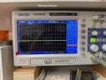
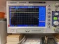
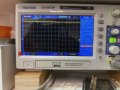
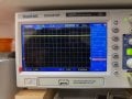
Thought I would try the scope (which I'm not entirely sure how to use yet). The output at the junction of D4/D5 is 5 volts with the momentary switch and is 7 volts with the transmitter switch. Would this make any difference?
Just about to ask using the scope.
Not really as the servo is powered by the 7.2 volt battery.
Put the scope on terminal #2 on the low level electrode with the servo ON.
Did you try R7 at 33K?
I cannot do the circuit in #124. Do not the parts.
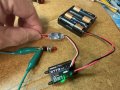
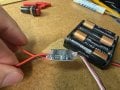
Just want to be clear. It is not a servo. It should not matter, this device (Electronic switch), is plugged into the receiver and turns on and off when the transmitter is toggled to turn it on and off. The receiver is powered by it's own 5v source. The bilge pump circuit is powered by a separate source (8v). The electronic switch is acting as a relay kinda. It gets power from one lead 3-30v and outputs in this case 7v to the load. In this case the source is the same 8v.
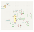
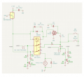
Not sure what happened. I'm back to the below circuit.
When low probe is in the water, LED2 on, pump off.
Put upper probe in, LED3 comes on but there is a 5-10 second delay for the pump to come on. Did not do this before, pump always came on immediately. AND, when upper probe is removed, the pump goes off, it should not go off until lower probe is removed.
With probes out of water, activated 'servo', LED goes on, see the scope pic, measures 7.6 volts on the meter.
Then something is definitely wired wrong.
Need to double check the connections.
Does the relay and motor activate immediately when manual is pressed and using the transmitter?
When you have time.
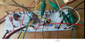
I see on your breadboard a red wire that appears on one end connected to pin8 of the relay.
What is this wire and what is connected on the other end?
Good eye!! That was the problem!! That wire is the signal coming from the electronic switch. I had it connected directly to pin 4 when it should have been connected to the junction of D4/D5. LED2 now is off when SW1 or SW2 is active. And the pump comes on immediately.
Now to figure out the problem when the probes are inserted and the pump delay. LED2/3 come on when they are supposed to but there is the 5-10 delay for the pump to turn on.

 Facebook
 Google
 GitHub
 Linkedin