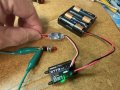
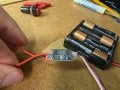
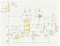
When low probe is in, LED2 on, pump off
When low and high probe in, LED2 on, LED3 on, pump on, LED1 on
Remove high probe from water, LED2 on, LED3 off, pump on, LED1 on
Remove low probe, everything goes off.
This is how it should work, yeah.
Tested the other parts.....
When I press SW2, LED1 is on and pump is on. LED2 has a very very slight flash to it.
When I use the transmitter SW1, the pump and LED1 is on and oddly LED2 comes on, it should not be on.
The radio receiver is connected to an electronic switch which reads the PWM signal from the receiver. The channel on the transmitter is like a toggle switch, so it is either on or off. I tried the input power to the electronic switch from 5v from the circuit and the 8v from the power supply.
Possible the transmitter is too close to the breadboard especially with all those wires around.
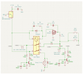
Try adding 100nf capacitors C3 and C4 across resistors R7 and R8.
This only happens on LED2, correct?
What is the closes size you have on hand to a 1uf?
If you remove that yellow jumper from R3 to the main board does LED2 still come on when transmitting?
Yes correct.
I'll check again in the morning. Have electrolytic caps that I did not check if one of those might work?
Have to call it quits for today. I'll try again tomorrow.
Appreciate your help and sticking with this. Almost there.
They tell me the probes are active or detect water. I could do without them as while the boat is in the water they cannot be seen. It appears they do complicate the circuit.
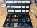
Here are some caps that I have. I have other scattered single ones not in this kit.
Well, if the motor is running then the probes are doing their jobs. No? I have to re-read the posts but I thought I saw where you said the motor runs and shuts off as it should but LED's keep staying on when they, too, should be off. Have I gotten that wrong?
Does that mean the motor worked as you wanted it to? To come on when the high limit probes activated the relay and stayed active until the low limit probes lost contact with water?
One side point about your probes: Since there's a possibility that a residual film of water may be falsely activating parts of your circuit - coat the insulation with wax. But don't bridge the two probes with water as a drop of water could hang onto the wax and create a pathway for the probes to think they're immersed.
END EDIT
OK will give something a try.
Yes on the PCB. Using KICAD for the first time so have a learning curve there. I usually etch my own, might try a service someone else I know uses.
Well, if the motor is running then the probes are doing their jobs. No? I have to re-read the posts but I thought I saw where you said the motor runs and shuts off as it should but LED's keep staying on when they, too, should be off. Have I gotten that wrong?
Correct. Before I started this episode with the addition LED's it worked fine thanks to sghioto. I'll try the 4.7 or 10uf as he suggests. Since it has complicated the project, it might be easier to leave them out. That would make the PCB less complicated.
Does LED2 come on when the manual button is pressed?
Another suggestion is connecting a capacitor from terminal #2 to ground on the low level electrode.
Starting with a 100nf and see if that works.
I believe the problem is the wiring layout on the breadboard acting as an antenna.
Once it's on a pcb the problem may not exist.
Remove the low level probe wiring from the breadboard and see if the problem still happens.
Reduce the value of R7 to 33K on the base of Q2.
Another option using a LM393 comparator chip.

 Facebook
 Google
 GitHub
 Linkedin