And that is only driving the LED2 circuit.
3.8 volts indicates the resistance of the probe in the water is appx 31.5K ohms.
That's close to what I read using tap water with an ohmmeter.
Are the probes nice and clean?
Maybe connect terminal #1 of both probes to the 7.2 volt battery source.
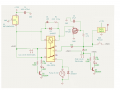
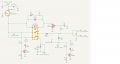
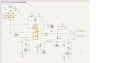
Thanks. Here is mine. I still have R7 & R8 in place. I added 2 pin connections where the battery connects, where SW1/2 connect and for the probes. It should bring over pads for those points to the PCB I think. Pretty sure I have footprints in place, might have to change them for C1/2. For some reason the ERC said PWR-Flags were needed.
6 volts is fine but the regulator may not function properly with a supply of 8 volts as the dropout voltage is typically 2 volts.
A lower dropout regulator is recommended.
The min input voltage for U1 is 6.5v. Specs Before designing this I was going to use a 6 cell NiMH pack. Even that may cut it close should the 6 cell pack get low. I can go to an 8 cell pack or maybe save some weight with a small 3s Lipo pack.
I can also keep the pads for the current U1 and add the pads for a 7806, they would be in parallel so I can decide anytime which one to use.
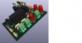
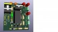
Did some cleanup and minor changes. Going to extend the board end by R7/8 so the pump can be mounted to the board.
Found the following...
7806/heatsink - 5.4v at the pump, circuit draws 295ma
RBT10W - 4.86v at the pump, circuit draw 186ma
There was no significant, very slight, change in the water flow from the pump. So I'll stick with the RBT10W but I'll leave the 7806 position in the PCB.
Any KICAD experts? I'm a bit confused. I think I found the answer online.
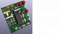
The F.CU layer is the Front/Top copper layer (RED). And the F.CU layer is the side the components go on. I think I have my traces on the wrong side. The red traces, which are the majority of traces, should be on the B.CU layer. And any of the blue traces I have should be on the Front/Top layer. I know it can go either way, but I think I need to flip the traces, right?
And I cannot seem to get the TL2285EE (SW1) switch to appear in the 3d view. That is not so important but I'd like to have this complete.

 Facebook
 Google
 GitHub
 Linkedin