Need Help Enabling External 0–5V Control on JIHPUMP KY300EL-I/104KA Peristaltic Pump

Thread Starter

mythpat

Joined Jun 8, 2026
2
Hello everyone,

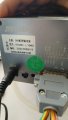
I am trying to automate a JIHPUMP KY300EL-I/104KA peristaltic pump using an ESP32. According to the rear-panel pinout and documentation, the pump supports external speed control through 0–5 V, 0–10 V, and 4–20 mA inputs. I have verified that Pin 14 provides approximately 5 V and Pin 12 is GND. However, connecting Pin 14 (+5 V) to Pin 9 (0–5 V input) does not appear to affect pump speed, and the front panel remains in control.

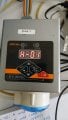
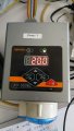
A major source of confusion is that the controller firmware does not match the manual. Pressing SET cycles through parameters H01–H14 (with H06 missing), and H05 displays "-88-". Several parameters have selectable ranges, but changes seem to revert after power cycling. I cannot find any documented method to switch from manual/local control to external analog control.

Has anyone worked with this specific controller or a similar JIHPUMP KY300EL series pump? Does anyone know the meaning of the H01–H14 parameters, or the procedure required to enable external 0–5 V control through the DB15 connector? Any documentation or experience would be greatly appreciated.

(I have obtained the official KY-300EL-I/104KA manual, but the documented OLED interface and mode-selection menus do not exist on my unit. My unit uses an LED display and an H01-H14 parameter menu instead.)
 

Attachments

Last edited:

Irving

Joined Jan 30, 2016
5,195
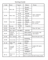
According to the KY300EL manual (link as too big to upload), you need to configure it for external control before the inputs are recognised. Pages 10 onward show how to make the relevant selections. [Edit] Ah, you need the manual for an older version with LED display...

Working on the assumption that the software is common across different models their other LED models give this chart.;.. try it and see...

1780916068447.png
 
Last edited:

Thread Starter

mythpat

Joined Jun 8, 2026
2
According to the KY300EL manual (link as too big to upload), you need to configure it for external control before the inputs are recognised. Pages 10 onward show how to make the relevant selections. [Edit] Ah, you need the manual for an older version with LED display...

Working on the assumption that the software is common across different models their other LED models give this chart.;.. try it and see...

View attachment 368133
Thank you, it's been really helpful.
 

MisterBill2

Joined Jan 23, 2018
28,013
Based on post #1, I suggest that the TS carefully examine the circuit to locate the correct inputs for the external control voltage. My take from post #1 implies an error in the connection for external control voltage.
 

BeablossomR_

Joined Jun 4, 2026
27
Hello everyone,

I am trying to automate a JIHPUMP KY300EL-I/104KA peristaltic pump using an ESP32. According to the rear-panel pinout and documentation, the pump supports external speed control through 0–5 V, 0–10 V, and 4–20 mA inputs. I have verified that Pin 14 provides approximately 5 V and Pin 12 is GND. However, connecting Pin 14 (+5 V) to Pin 9 (0–5 V input) does not appear to affect pump speed, and the front panel remains in control.

A major source of confusion is that the controller firmware does not match the manual. Pressing SET cycles through parameters H01–H14 (with H06 missing), and H05 displays "-88-". Several parameters have selectable ranges, but changes seem to revert after power cycling. I cannot find any documented method to switch from manual/local control to external analog control.

Has anyone worked with this specific controller or a similar JIHPUMP KY300EL series pump? Does anyone know the meaning of the H01–H14 parameters, or the procedure required to enable external 0–5 V control through the DB15 connector? Any documentation or experience would be greatly appreciated.

(I have obtained the official KY-300EL-I/104KA manual, but the documented OLED interface and mode-selection menus do not exist on my unit. My unit uses an LED display and an H01-H14 parameter menu instead.)
It sounds like the pump is still in local (front panel) control, so it’s ignoring the external 0–5 V input. On many pumps like this, you have to change a parameter to switch the control source from “panel” to “external analog.” Your H01–H14 menu is likely that settings menu (just a different firmware than the manual), and one of those values should control the input mode. If your changes don’t stick after power cycling, there’s probably a save step, like holding the SET button.
Also, connecting the built-in 5 V pin directly to the input won’t really “control” speed it’s just a fixed voltage. The pump usually expects a variable analog signal (like from a DAC or filtered PWM). This page explains the idea simply: Analog signal (Wikipedia)
So most likely, you just need to enable external control in the parameters and then feed it a real adjustable 0–5 V signal.

https://en.wikipedia.org/wiki/Analog_signal?
 

MisterBill2

Joined Jan 23, 2018
28,013
It does sometimes happens that a manual neglects to include some vital step that is required by the design team but that the manual writing team is not aware of.
This seems like it may be the case here.
 
Last edited:

Irving

Joined Jan 30, 2016
5,195
@MisterBill2 Neither of your previous assertions are true. The TS identified the correct connections as documented on the rear panel label but was unable to enable the remote input option as the manual available on the manufacturers website is for the updated version not the older one which is no longer manufactured. However they still sell an older version of a different model so surmising that they reuse the same software across the range I extracted the relevant info from that manual for the TS and that appears to have worked.
 

MisterBill2

Joined Jan 23, 2018
28,013
If some variable voltage within that range were applied the result might be different. Possibly 2 volts would provide a lower speed.
It is also quote possible that some other action is needed to allow an external voltage to control the speed.
The fact is that not all of the information was provided, so the response was a guess.

IN ADDITION, the application of a maximum voltage to an analog input may trigger some undesired fault recovery mode. some control systems are designed to have automatic protection agains what they see as faults.
 
Last edited:
That makes sense. It looks like the issue wasn’t the wiring but a documentation mismatch, the TS had the correct connections, but the available manual was for a different version. Good catch using a similar model’s manual to fill the gap. Without complete info, earlier suggestions were really just educated guesses, and there may still be an extra step or setting needed to fully enable external control.
 

Reloadron

Joined Jan 15, 2015
7,905
I am trying to automate a JIHPUMP KY300EL-I/104KA peristaltic pump using an ESP32. According to the rear-panel pinout and documentation, the pump supports external speed control through 0–5 V, 0–10 V, and 4–20 mA inputs. I have verified that Pin 14 provides approximately 5 V and Pin 12 is GND. However, connecting Pin 14 (+5 V) to Pin 9 (0–5 V input) does not appear to affect pump speed, and the front panel remains in control.
I have a question. I see mention of using an ESP32? That's fine and the ESP32 by my understanding is a 3.3 volt device. You can get an analog voltage out using D to A but the ESP32 using D to A is an 8 bit device. So on an ESP32 using its analog out with the 3.3 volt reference all you have is 0 to 3.3 volts out in an 8 bit format. You will never get a 0 to 5.0 volt signal for your pump. Your best resolution will be about 12.9 mV per step change.

What am I missing here?

Ron
 

MisterBill2

Joined Jan 23, 2018
28,013
Like has been mentioned, I think, an analog voltage speed control will need to be enabled somewhere in the control software. AND you might need to change a jumper deep inside the device. Just because some optional feature may be available for some model device doews not mean it is available on all production units of that model.
THIS is when it is a serious benefit to have a detailed product user manual available. It might be possible to work with a supplier oof that product to get soame information, maybe..
 
Last edited:

panic mode

Joined Oct 10, 2011
5,176
I have a question. I see mention of using an ESP32? That's fine and the ESP32 by my understanding is a 3.3 volt device. You can get an analog voltage out using D to A but the ESP32 using D to A is an 8 bit device. So on an ESP32 using its analog out with the 3.3 volt reference all you have is 0 to 3.3 volts out in an 8 bit format. You will never get a 0 to 5.0 volt signal for your pump. Your best resolution will be about 12.9 mV per step change.

What am I missing here?

Ron
use controller to control, but when needed add other parts to accomplish the goal. single OpAmp can translate 0-3.3V to 0-5V or 0-10V.
as for built in AD-DA i rarely use them, they are noisy and usually only low res. MCP4725 is 12-bit, common and very low cost. without trimpots, 1% metal film resistors will get almost perfect full range (0-9.9V). of course there are more granular resistor series and trimpots but i would not bother. and if one wants to nitpick, perhaps go for 47k/100k for R14/R15 to get up to 0-10.3V. this way one can get to actual 0-10V even when resistor tolerances are against you, plus easy to cap in software. resistor at output is for protection against short circuit (wiring faults, cable failure). this does not affect gain since feedback is around it.

1786684052796.png
 

MisterBill2

Joined Jan 23, 2018
28,013
An op-amp to scale that 3.3 volt signal up to 0- 5.0 volts can work properly
BUT if you will never need to go to a value below 2.7 volts, just adding a 2.7 volts offset in series is a second option. NOT THE BEST, but it can work when you do not need the lower value.
 

MisterBill2

Joined Jan 23, 2018
28,013
not sure i follow... i understand the offset idea but ... where did 2.7V value coming from? if DAC output is 0-3.3V, adding 2.7V offset will move range to 2.7-6.0V.
The 2.7 volt offset was to allow the control voltage to reach5.0 volts when the max from the controller was at 3.3 volts. Ofcourse, actually the added offset would only be 1.7 volts. It seems that there was a slight error on the math earlier. Thanks for catching the error!
 

panic mode

Joined Oct 10, 2011
5,176
i guessed it was a typo meant to be 1.7V but... better ask than assume. one can do offset/scaling using different means (such as using zener and pullup resistor). but since standard zeners do not exist (to my knowledge) in 1.7V variety and using other diodes is not as robust, the cleanest offset would still use OpAmp. and if one has OpAmp, may as well use it to cover full range.
 
Last edited:
Top