An unusual error in my hacked DMM FS8233

Thread Starter

q12x

Joined Sep 25, 2015
2,227
Very cool simulation mister @Danko !
Aaaaaaaah I think I know what you did there. You used my second oscilator example, the most common flip flop one. Good idea !!!!
I almost make it work on mine - in reality. I am giving up on the zener shunt and replace it with an AMS1117 VReg set at 3V.
This means I will take those 5V directly from that SMPS and transform them into this floating Voltage, THEN transform the --whatever-- output V after the secondary coil through the rectBr with this VReg into 3V.
CLEAR AS MUD? Haha
But it might work. And hopefully will add some safety in the same time.... Im not completely trusting this AMS1117 against spikes... I hate spikes (personal opinion here) I had a lot of troubles from them and STILL not good at dealing professionally with them. Eh well...
OR..should I still include that zener shunt as an extra measure of safety? in my poor simulation I see some spikes even with that shunt. It's not perfect. But what is, right?
 

Thread Starter

q12x

Joined Sep 25, 2015
2,227
Aaaaaaaaaaand, fail again. Hahaha.
I actually test it on the DMM. It did worked at 3V as expected, no problem.
BUT... no sufficient amperage for optimal work of the DMM. I encounter this problem before, when I was putting resistors in series with the 3V wire, remember my list of multiple permutations? Well, OVER 100R on the wire, the device will start beeping, as a signal that the current is way too low. The same thing happened right now with my circuit. Lucky me that I tested those resistors before !!!! Very lucky. Because now I can identify exactly what the problem is.
So... basically, I need more juice.
My little transformer in this cct did output some 12V. Then I put that into AMS1117 and transform it into 3V. That 12V I leave it like that specifically having in mind a bit more current from them after the 3V... but that is not really enough either. Probably... a better transformer? But how? My thinking is to use thicker copper wire. On the secondary? Im really in the woods right now. And Im tired of it. What a disaster !
 

bigkim100@

Joined Oct 25, 2022
3
Or, bounce the damn thing off the edge of the trash bin, and buy a Fluke that will last for years with a standard 9v Battery...hell Im on year 4 with mine (Im so anal, I label them)
 

panic mode

Joined Oct 10, 2011
5,175
DMMs use little power and there are ready made isolated converters. if learning and tinkering is the objective (and that seem to be the case judging by your collection of small transformers) then you can use any of the small audio transformers. since htey are meant to drive low impedance speaker, secondary has far fewer turns than the primary. but nothing stops you from using identical second transformer and wire it back to back with the first one.
1668002728658.png
 

DickCappels

Joined Aug 21, 2008
10,662
Amazing -You have made amazing progress while I distracted.
If you are already getting 3 volts out then you will not need this:

Transformer windings:
The voltage on a winding is proportional to the number of turns. If you are feeding the primary with 5 volts and you have 20 turns on each side of the center-tapped winding then the peak volts per turn on the secondary will be will be 5V/20T = 0.25 volts per turn.

Allow 0.7 volts for the forward drop in the rectifier, meaning you will need 3.7 volts peak on the secondary winding.

3.7 volts/ 0.25 volts per turn = 14.8, call if 15 volts on the secondary. You may have to add or subtract a turn or two to account for small influences that we neglected here.

Cores:
I looked at your pictures of cores. I do not recommend ferrite bars - they are great for transmitters but here you want to keep the energy in the cores, not broadcast all over the neighborhood :) Not that 10 or 20 kHz will interfere with anything important, but it is good form to keep your power inside your core except when you intentionally take it out through a winding.
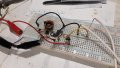
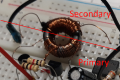
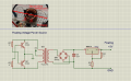
I think I saw E-E and or E-I cores in your photographs. Those would be the ones to try first. Most of the toroids look like they might be RF ferrite (a guess) so I would try them last.

Off The Shelf Transformers:
I am not going to recommend an off-the-shelf transformer because searching for one would entail countless hours and I think you know what to look for now.

Emitter-to-Base Voltage Shunt Diodes
Those diodes are a good idea to protect the transistors from a reduction in current gain because of consistent reverse avalanching of the emitter-base junction. Most 2N2222 transistors have a reverse Emitter-Base voltage rating of 6 volts. If your base waveform does not exceed -5 volts peak then you are pretty safe omitting the diodes. This first time around the diodes are a reasonable precaution -why take chances?
 

Thread Starter

q12x

Joined Sep 25, 2015
2,227
Thank you for the explanations !
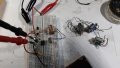
Here is how it looks so far. It worked fine from the first try. But after that....
20221110_011952.jpg
The story is way too long. I tried probably 10 new windings for secondary alone. With 3 different diameter wire, different length wire, 1meter or 50cm. I also used some scrapped enameled wires and they give me problems because the enamel was off in some locations and most probably they touched and created coil short, rendering the output at very low voltage <1V. I tell you, a LOT of permutations for the secondary alone. I know all of these things but not enough practice.
On the primary, I changed its coils as well. I basically soldered in continuation of the 20 windings, another 20(probably). But with some nasty surprises. I got the transistors extremely hot. They are BC548. The amperage through the circuit, that I read from PSU screen, was around 300mA. Sometimes reached 500mA. I changed them with BD139. I got 1A, Im not kidding. What the hell? So I realized, slowly but surely, that the increased windings in the primary (these 2 center tap coils) was throwing back a lot of current into my 2 transistors. Pretty much their respective maximum power for each. 300ma for BC548 and 1A for BD139. They were fully open in a sense and conducting the most they could.
1668036773018.png
I turned back to the original winding 20turns per coil-as shown in the images attached. Then I played with the resistors. I reached 100R on their bases and they got again extremely hot. I put 10k after that. I was mistakenly believing that my PSU amperage is for the --entire-- circuit. But it is not! It is only for the first part of the circuit, including primary coils. But secondary coil and the other side of the circuit, was having it's own amperage that I never checked. I only checked the voltage of it!!! You get used to make 100 mistakes until you get 1 correct answer.
I still dont know how to increase the amperage of THIS circuit right here. BUT...I might have a solution. By doubling the entire circuit and in the end linking in parallel the 2 output of 3V.
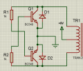
Here is the circuit I used and tested so far:
1668039108725.png

Now, reading your last comments I realized that I never thought to include back EMF protection diodes for the CE of the Tr's. What an idiot I am. That most probably may be one of the reasons all the Tr's were getting very hot ! Hmmm. It might be.
Like this:
1668039901414.png
- I also tested directly on the DMM in various occasions in my many experiments, (making sure all the time there are 3V in my output) and he was always beeping, signalling me that the current was too low. Thats how I realized the current in the secondary was not changing at all (or insignificatively small) and that PSU reading was in fact for the 1st half of the circuit.
- Im not giving up on this circuit yet. It is a VERY pretentious circuit. I give you that. I still believe I can optimize it to give me what I want. More juice, more current. I plan to get into measuring it more seriously this round. And if Im right, those measurements will guide me to the right answer. I also plan to add in the game, my Frequence Counter !!!!!!!!!!! Tadaaaa.... Hopefully it will tell me more whats going on. Also, more osciloscoping.
 

Attachments

Last edited:

DickCappels

Joined Aug 21, 2008
10,662
There is a good chance that the inductance of your primary is too low, which suggests that you need to look for a core with a higher inductance per turn squared. Either that or add a heck of a lot of turns to the primary. Maybe 100 Ohms is a bit low for the base resistors, I think you were going in the right direction.

With a load of a few milliamps nothing should get hot. Warm maybe but not hot.

I doubt that emitter-base avalanching is responsible for things getting hot. It should not be happening with the few volts you have on the primary winding.

Do you have a way to measure the frequency?
 

Thread Starter

q12x

Joined Sep 25, 2015
2,227
Do you have a way to measure the frequency?
So you also think is a good idea. I have a DL4YHF frequency counter, this yellow version.
1668049600579.png
I doubt that emitter-base avalanching is responsible for things getting hot. It should not be happening with the few volts you have on the primary winding.
It might be the --numbers-- in coil windings as the actual amp killer. Because I double them from 20 to ~40 per each side. But now when I see those diodes mentioned, I spit and slap on my ass, I didnt think of it. It might be some sort of strong feedback that these Tr's were experience. OR, the other very possible reason, the coils themselves are also scrapped and they may have touch through holes and short ! That creating a -no coil- situation, so, full current through C-E. The moment I got off the extra coils and revert to original 20, it worked normally. Thats because the windings are one after another in a single layer, and NOT one on top of the other to permit shorts. It is partially my negligence here, I admit. Also I present possibilities. It might be this or that cause. I will try to add a more serious protection layer between coils this time. And winding back to 40 per coil in the primary. Hopefully, this should add more juice amperage in the secondary. Its all the theory I know, haha.

With a load of a few milliamps nothing should get hot. Warm maybe but not hot.
You are making the same mistake as me. Believing this is a full circuit. It is 2 circuits split in half by that transformer. So the LOAD, is in the second half of the circuit. That 2nd half is only reacting from the first half but not influencing anything in the primary, only in its secondary side. Nothing got hot in the secondary circuit. Only in the primary. In the secondary I got the problem of not getting any voltage or <1V suggesting a very possible short in the scrapped coils I used. Damn those coils. Haha.
 

Thread Starter

q12x

Joined Sep 25, 2015
2,227
My all concentration today will be to monitor and lift up the current in the secondary cct.
I just did a preliminary test right now, with the working circuit (20 windings for each coil in primary) and whatever windings in the secondary -1meter length of wire actually-.
This is the data and I should have read all of this from the very beginning. Im not used to. Im too lazy.
Primary 5V @ 80mA -I read this from the PSU screen. Remember that before, I was believing this numbers are for the entire cct. Im glad I made the difference. Its stupid simple but I dont see everything in one shot.
Secondary 3V @ 1.31mA this 3V is AFTER the Vreg. The original voltage imediatly after the BrRect is 11.20VDC rectified.
At least 10mA. And 100mA would be best.
Ill try to reach this new target today, of 10mA in the secondary. Wish me luck and also put ideas on the table here.
 

Thread Starter

q12x

Joined Sep 25, 2015
2,227
Im doing something wrong and no one here is telling me what.
I put AGAIN another round of wires over the primary. This time I put some good isolation between 1st layer of windings and this new one. But I used the old used scrapped wires as before. I wind like ~20 more. So now is having 40 windings per each coil.
This time I didnt have that over-current over-heat on the transistors ! Last time I did. This tells me that I had a short for sure.
But this time, was very ok. The only problem is that no significative increase in the amperage in the secondary.
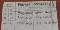
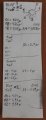
These are the notes I took:
20221110_065910.jpg
The last column means DC Voltage on the BrRectifier.
I was expecting 1.41mA on the last line. I probably have another short there. But the general Amps in the primary got down to 40mA. So...I have no idea what to think.
I dont think I can reach 10mA with this transformer I have here.... very frustrating.
But im happy I can measure everything and have a good enough overview over the entire circuit.
Please suggest me what transformer to use from all that pile I have. Show me an image on the internet and I will compare with what I have. At least.
Thank you. I am really in the woods with this subject. My intuition can go so far.
 

DickCappels

Joined Aug 21, 2008
10,662
Unless you have a way to measure inductance you are pretty much stuck with trial and error.

Look on the bright side: You are way past trying to get it to work and are on to optimizing the design.

Did you notice that in post #52 Danko demonstrated that if all windings you automatically get about 3 volts out and no power lost in the regulator?
 

Thread Starter

q12x

Joined Sep 25, 2015
2,227
Did you notice that in post #52 Danko demonstrated that if all windings you automatically get about 3 volts out and no power lost in the regulator?
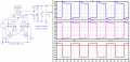
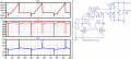
I only see spikes in his scopes which means that circuit is not good.
He is demonstrating how it looks without those back EMF diodes he added in his previous simulation in #41.
 

Thread Starter

q12x

Joined Sep 25, 2015
2,227
I made a discovery !
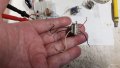
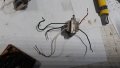
I find that I already have some very small transformers:
20221110_094543.jpg20221110_094525.jpg20221110_094456.jpg
I find only these 4 with the same wire configuration.
I tested all of them. None worked.
I checked their windings if 1-are uninterrupted and 2-what resistance they have.
so...
20221110_105641.jpg
I believe the red is damaged. I couldn't get consistent readings from it.
Both the blues are reading high resistance so they must be like that from design. I was thinking maybe the blue #1 was over stressed. But when #2 confirmed the same readings, then... it must be ok. I tested it and the circuit is not working.
The winner from all of this is definitely the green one. I install it into the cct. And... it kind of worked. I got 0.4V on the rectified DC side. Its very small but is something. Is telling me these transformers are working. At least the green one. But in the primary side, I had to change the 2 Res into 100R and the tr's got hot-ish. i dont like them this hot, but for this test is fine.
So... failed again.
I start to believe this circuit is not good. Or at least is so specific, that I have little to no chance to make it work. Not even with you guys here in the forum. This sucks.... Ill have to find some alternative circuit for this floating voltage !
 
Last edited:

Danko

Joined Nov 22, 2017
2,222
I start to believe this circuit is not good. Or at least is so specific, that I have little to no chance to make it work. Not even with you guys here in the forum. This sucks.... Ill have to find some alternative circuit for this floating voltage !
You can solve problem with converter.
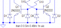
1. Use this circuit:
1668071304495.png
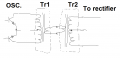
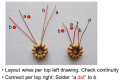
2. Wound primary bifilar,
spread turns evenly by surface of ferrite ring,
else you always will have spikes:
1668068768687.png
3. All 3 windings should contain same number of turns (20, for example).
 
Last edited:

Danko

Joined Nov 22, 2017
2,222
Can a twisted wire substitute as a bifilar wire?
Twisted pair usually used in RF transformers
for wide frequency response. (Link to PDF)
In your transformer copper of wires should be as close each to other
and to ferrite surface, as possible, with thin insulation (not plastic thick one).
Use two enameled magnet wires in parallel.
 
Last edited:

Thread Starter

q12x

Joined Sep 25, 2015
2,227
Use two enameled magnet wires in parallel.
2 enameled copper wires in parallel is called a bifilar wire. I do not have any of it. But I can twist some normal enameled copper wires. So... it will work? Or you are not sure. Ok then.... I will try to glue together 2 wires in parallel and make myself some DIY bifilar wire.... if I can. All I can do is to try, right?
 
Top