 Facebook
 Google
 GitHub
 Linkedin
Korg microKorg E.2.1 Error - No Sound, Output Thumps, Service Tests Fail
Work Done So Far
Power supply recap:
Audio behavior:
- When audio is input to [audio in jack #2] the led #6 will flicker and VR will change input level.
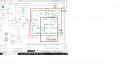
Need Help Understanding where to look next? Is IC14 supposed to be ground-side control to produce the sounds since pins 2-5 have 2.5volts? I have a rigol DHO802 scope, I see a lot of activity from the DSP, I am however no expert at confirming if its sending the right data. DSP IC17 has power, ground, clock, shows communication with IC14 ((AK4522VF). DAC IC14 has power, ground and square wave on pins 10-13. Pins 2-5 have 2.5 volts. I really need help trying to pin down both the DAC and DSP, I'm thinking those are the most likely suspects, but then again it may be something else. I've attached the service manual, If anyone out there knows how to help me diagnose further, it would be greatly appreciated.
Work Done So Far
Power supply recap:
- Most electrolytic capacitors replaced with equivalents, A lot were out of spec.
- Power rails now measure stable (no voltage drops noted at any ic's)
- Mode 1+3 (Auto) gives E.2.1 error (also displays Rom ver 1.03)
Audio behavior:
- When audio is input to [audio in jack #2] the led #6 will flicker and VR will change input level.
- No sound output from any patch, no sound from keyboard, no sound from input #2.
- Demo mode will start and switches patches 1-8 and a pop can be heard between patches. No popping from audio input.
- Previous owner mentioned: vocoder failed first, then total silence
Need Help Understanding where to look next? Is IC14 supposed to be ground-side control to produce the sounds since pins 2-5 have 2.5volts? I have a rigol DHO802 scope, I see a lot of activity from the DSP, I am however no expert at confirming if its sending the right data. DSP IC17 has power, ground, clock, shows communication with IC14 ((AK4522VF). DAC IC14 has power, ground and square wave on pins 10-13. Pins 2-5 have 2.5 volts. I really need help trying to pin down both the DAC and DSP, I'm thinking those are the most likely suspects, but then again it may be something else. I've attached the service manual, If anyone out there knows how to help me diagnose further, it would be greatly appreciated.
Attachments
-
920.6 KB Views: 5
![20260402_071317[1].jpg](/data/attachments/353/353139-42f277c82853891ec0b83d8285556477.jpg)
![20260402_071354[1].jpg](/data/attachments/353/353140-9a2e37b2e2babd5fb267b9d68b639f51.jpg)
![20260402_071437[1].jpg](/data/attachments/353/353141-958fdafffe75502301f5e97ef63dab57.jpg)
![20260412_194630[1].jpg](/data/attachments/353/353518-5e77a2e1119572054aa9bf3dcae3492d.jpg)
![20260412_194642[1].jpg](/data/attachments/353/353519-4ab59064723fcaddac8a205c1be7f76e.jpg)


