An unusual error in my hacked DMM FS8233

Thread Starter

q12x

Joined Sep 25, 2015
2,227
We are NOT in synchronous experimentation here, at all. Let me synchronize it for you then.
I just made the same experiment as you did in yours. It took me awhile. I should have been more quick.
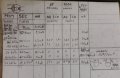
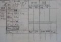
I put myself a LOAD resistor of 100R. You can see it in my table as well. And tada.... I get 19mA in the secondary cct. But as you guessed, at the price of lower voltage, 1.78V.
IMG_20221112_202857.jpg
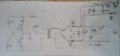
The AB and CD are the Voltage measuring points. CD in my care is AFTER the VReg output. You can barely see it in the skematic.
IMG_20221112_202910.jpg
Miss @sarahMCML , please make a Voltage measurement with and without the Load resistor.
Also please specify at which points in the cct you took the voltage measurement.
You will see that with no Load, you will get down to a couple of mA as I did all this time. Probably around 2mA because something in your cct is better than here in mine. I got a max of 1.35mA and now Im running it at 1.2mA.
 

sarahMCML

Joined May 11, 2019
703
We are NOT in synchronous experimentation here, at all. Let me synchronize it for you then.
I just made the same experiment as you did in yours. It took me awhile. I should have been more quick.
I put myself a LOAD resistor of 100R. You can see it in my table as well. And tada.... I get 19mA in the secondary cct. But as you guessed, at the price of lower voltage, 1.78V.
View attachment 280523
The AB and CD are the Voltage measuring points. CD in my care is AFTER the VReg output. You can barely see it in the skematic.
View attachment 280524
Miss @sarahMCML , please make a Voltage measurement with and without the Load resistor.
Also please specify at which points in the cct you took the voltage measurement.
You will see that with no Load, you will get down to a couple of mA as I did all this time. Probably around 2mA because something in your cct is better than here in mine. I got a max of 1.35mA and now Im running it at 1.2mA.
Remember, I don't have a 3.3V regulator in my cct, just the Schottky diode bridge and a smoothing capacitor, across which I'm measuring my output voltages. With NO load resistor connected, I measure 6.05V out, and my circuit is taking 73mA from my PSU at 5V input.
My previous post showed voltages and currents at 2 different loads.
 

Thread Starter

q12x

Joined Sep 25, 2015
2,227
and my circuit is taking 73mA from my PSU at 5V input
Oh boy, you really dont pay attention. I told you 3 times already. The circuit is split in 2 half. 1half of the circuit is indeed getting a high amperage and that is the oscilator side of the circuit. I got mine at 1A !!!! remember? Usually is like 100mA I dont even pay attention to it. That is the PSU powering only HALF of this circuit blestemat. THats 1 of the problem. You were telling me all this time the PSU power? Haha. No-no-no. Thats completely other story.
Oh boy.
 

sarahMCML

Joined May 11, 2019
703
Oh boy, you really dont pay attention. I told you 3 times already. The circuit is split in 2 half. 1half of the circuit is indeed getting a high amperage and that is the oscilator side of the circuit. I got mine at 1A !!!! remember? Usually is like 100mA I dont even pay attention to it. That is the PSU powering only HALF of this circuit blestemat. THats 1 of the problem. You were telling me all this time the PSU power? Haha. No-no-no. Thats completely other story.
Oh boy.
No, you're the one who isn't understanding my information.
When I disconnected the load from the output side, the 73mA current that I measured IS the current that the oscillator side alone is taking. There is NO current flowing in the rectifier side!
When I add the various loads, as previously shown, the supply currents increase, and the output currents are as noted.
 

Thread Starter

q12x

Joined Sep 25, 2015
2,227
My dear @sarahMCML; So... check this out. The PSU Amperage reading, is only for the half of the circuit. Until half of the transformer if you will. It is by no means your PSU is reading the amperage in the secondary circuit. You get me now? If you put the probes and measure the voltage in AB points, like you said you did, BUT you still read the PSU amperage, thats a big error ! I got trapped in it as well but I seen it in time. The secondary of the transformer and everything, all the circuit after that, has it's own amperage. Ok? You must do as I do, and literally break A point wire and insert in line an ampermeter and read THAT for the amperage in this circuit.
I hope Im clear enough. If you did already all the correct things, then I apologize, since it is indeed a very easy trap, and I repeat, I fall in it in the beginning.
1668307312013.png
On another pov:
- All the entire bad luck I had so far, all the fail experimentation, was because I got extremely cheap, and use some scrap wire I received from someone some time ago. THe large majority of it is having literally holes in the enamel, im not kidding. If I put 1 probe of the continuity tester, the one that beeps, on one end of the wire and with the other probe slide along the wire, at some random points I get the beep. So a lot of these wires were compromised and I worked like that knowing this fact, but hoping for luck. Luck did not cut it at all. And I know where it had the most chance to short all this time. Not on the OD - Outer Diametr of the coil. But in the ID - Inner Diameter of the coil, where all the wires are close together. And a very hard spot to isolate too, because it will grow thick very quickly. I'll most probably have to either find a way of isolating these used wires, painting it with some paint or laquer, or throw it away for good. Such a good diameter wires. aaah. And not all is bad, but the random holes in it makes it very unpredictable. And you cant see them, especially on very fine wire. Thats the biggest problem I fight with. I had to wind a couple of times and find its shorting, and unwind back and find it is working again with the original coil. I put windings on top the others that were good.
 

MisterBill2

Joined Jan 23, 2018
28,031
The quite high no-load voltage is because of a long standing problem with inverter power supplies. Those nasty voltage spikes drive the no-load voltage MUCH higher. That is how it happens. The simple filter acts like a peak detector and with the peaks being much higher those are the results. One solution has been better magnetic coupling between primary and secondary. That was reported by the author of a much higher power inverter project a few years back. But probably the same thing applies to a 2 watt supply as for the 2200 watt supply.
 
Last edited:

sarahMCML

Joined May 11, 2019
703
My dear @sarahMCML; So... check this out. The PSU Amperage reading, is only for the half of the circuit. Until half of the transformer if you will. It is by no means your PSU is reading the amperage in the secondary circuit. You get me now? If you put the probes and measure the voltage in AB points, like you said you did, BUT you still read the PSU amperage, thats a big error ! I got trapped in it as well but I seen it in time. The secondary of the transformer and everything, all the circuit after that, has it's own amperage. Ok? You must do as I do, and literally break A point wire and insert in line an ampermeter and read THAT for the amperage in this circuit.
I hope Im clear enough. If you did already all the correct things, then I apologize, since it is indeed a very easy trap, and I repeat, I fall in it in the beginning.
View attachment 280555
On another pov:
- All the entire bad luck I had so far, all the fail experimentation, was because I got extremely cheap, and use some scrap wire I received from someone some time ago. THe large majority of it is having literally holes in the enamel, im not kidding. If I put 1 probe of the continuity tester, the one that beeps, on one end of the wire and with the other probe slide along the wire, at some random points I get the beep. So a lot of these wires were compromised and I worked like that knowing this fact, but hoping for luck. Luck did not cut it at all. And I know where it had the most chance to short all this time. Not on the OD - Outer Diametr of the coil. But in the ID - Inner Diameter of the coil, where all the wires are close together. And a very hard spot to isolate too, because it will grow thick very quickly. I'll most probably have to either find a way of isolating these used wires, painting it with some paint or laquer, or throw it away for good. Such a good diameter wires. aaah. And not all is bad, but the random holes in it makes it very unpredictable. And you cant see them, especially on very fine wire. Thats the biggest problem I fight with. I had to wind a couple of times and find its shorting, and unwind back and find it is working again with the original coil. I put windings on top the others that were good.
No, I'm NOT reading the current at the AB points, I'm reading the current at the primary of the transformer, where the 5V goes in, and it is 73mA, with the secondary circuitry disconnected!
I don't need to put an ammeter in the secondary side of the circuit at point A because, unlike you, I don,t have any circuitry that is consuming any current. You have your 3.3v regulator and Zener diode/ transistor circuit which will take the small amount that you are seeing. My circuit just charges the capacitor to it's peak voltage, then current flow ceases.

EDIT: 73mA not 93mA (corrected)
 

Thread Starter

q12x

Joined Sep 25, 2015
2,227
to @sarahMCML - How did you wind the secondary (not the primary) in this bifilar way?
I mean, what did you do with the middle connection? Leave it in air and isolate it? Its the only thing I can think of.
Thank you.
 

sarahMCML

Joined May 11, 2019
703
to @sarahMCML - How did you wind the secondary (not the primary) in this bifilar way?
I mean, what did you do with the middle connection? Leave it in air and isolate it? Its the only thing I can think of.
Thank you.
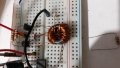
First, I took a long length of wire, folded it over in the middle back on itself, and used it to wind on 22 turns. Then I cut the common point, used my ohmmeter to find which were which of the 2 now seperate sections, and used the middle of one winding and the end of the other to make the new common centre of the primary.
Then I took a 3rd piece of wire and wound 22 turns over the top of the primary. This is the secondary, and there is no middle to this winding!

Out of interest yesterday I made another transformer using a toroid with dimensions almost the same as yours, except that it is only 3mm thick. This time I twisted 3 pieces of wire together using my drill, giving the combination about 5 turns/inch, then wound on 20 turns.
I then used 2 sections for the primary and the 3rd for the secondary, and just put it in place of the original one.
This one works better than the first.
 
Last edited:

Thread Starter

q12x

Joined Sep 25, 2015
2,227
Thank you for your answer miss @sarahMCML.
- I had to test the (bifilar windings in the Secondary) myself after all. It only worked with (a) linked to (a) wire and (b) linked to (b) wire. In a word, (aa-bb) the same wire connected to itself to create a pin. Very-very strange!!! I tried all the permutations possible, the normal bifilar b-ab-a, and inverse, a-ba-b, but I got a Hot/in Short Primary transistors and very high PSU 340mA reading for the Primary circuit. This 300mA level is boiling these small power transistors. If I were to put more powerful like BD139, it was jumping to 1A. The maximum the transistor can possible stay open. Thats why I call it a 'short'.
When you see 30turns or 60turns without 'bifilar' mentioned near, it means normal turns, like any normal coil winding. With 1one wire !
When you see 'bifilar' mentioned, it means b-ab-a connections of 2 wire side by side, in 30 or 60 turns, most of it in Primary. Exception in the secondary with that weird connection aa-bb, which was the only one that worked.
20221114_052033.jpg
20221114_052518.jpg
VERY HARD circuit. Deceptively simple !!! Extremely specialized !!! Thats my impression after staying on this transformer, literally for DAYS !!! I wind and re-wind the coils on this donut ferrite core MORE than 20 times !!!!! Or 30. Imagine how hard it is to undone your work and start again. Very hard. But I did it. And test after test after test.
I realized something very important! I was saying that my turns copper wires were in short. Not true after all this testing. Very deceptive circuit ! I start to believe it is some sort of maximum frequency in the primary that at some point is opening the Tr's full and creating the short, overheating them. And destroying them if not quick to kill the power in a short time. I actually let them to boil a bit. Still working ok when cold. Also... the number of coils in the secondary, will induce a saturation in the transformer and again, short. It appears as a short. But in reality is not truly a short. Thats the very new and weird phenomenon I observed. If I lower back the coils in the secondary, everything goes to work just fine as before. If I switch the coils between them, also, working just fine. But in the moment I add more wire to the secondary coil, bang, short. What I did with that bifilar connection in the secondary aa-bb in my picture, was lowering basically the coil/turn length. And it worked like that. In a very strange way, but it did.
The same exact thing is valuable for Primary coils. The more coils I add, especially if they are normal winding, not bifilar, the more amperage from the PSU rises and at some point, bang, short. If I lower the coils number, in the Primary, everything goes back to normal. This means a certain saturation of the transformer was reached. Also the frequency to open fully those transistors and create the short. Very strange.
There is a certain frequency of the entire transformer that is optimum to operate at. I dont know how to measure it. I only feel looks like it may be like that.
- This particular donut ferrite core likes very much only bifilar windings. The normal windings are not good, especially for higher number of coils. I didnt really try with small number of coils.... Very Hard circuit !!! to drive. It only likes one special way and I probably got close to that special way, but I was dealing with other problems in the way and now when I look back, I think I might have get close. But it is a limited power that I can milk from the secondary. Not as much as I expected. Pitty.
- Also I had very strange and unrepetable results along the way. Sometimes I got increased amperage while increasing the voltage, like those AB and CD points I was measuring and NoLoad and 100R load; and other times, doesnt matter how high the number of coils I put, the V and A was staying the same in the secondary, and only in primary was a difference. What a sh**. Very-very-Very different results. I also did a lot of diferent windings and not all I put them down on the paper table. Its impossible to keep track or remember everything.
These are my personal conclusions and experiments and way of seeing things. I may be wrong or not correctly interpret some parts of it. For sure. Simply because this side of electronics is unknown to me. Im not THAT good at it. You know.
So it is a fail again. Meaning that I didnt reach the 10mA goal in the secondary. I also tested the DMM power and always beeping that is not enough mA to power it.
Either I need another circuit or another idea how to power this DMM. THis circuit here failed to do it and I am sick of it.
 
Last edited:

Thread Starter

q12x

Joined Sep 25, 2015
2,227
Are the 2N2222's saturating when the transistors are supposed to be on?
Im using BC548 NPN 45V 100mA 625mW
Im not sure how I can actually test this part of a transistor. I mean for an optimized On state - the perfect point or range, when is perfect On. Not a bit lower, not a bit higher. THat I can see when varying the current though its base. But never could find a way of reaching its perfect balanced ON state. You know? But thats completely another story.
I believe it's an avalanche whats happening there. Specifically at that 300mA level.
Importan NOTE: 100mA in it's datasheet it's the Maximum SAFE parameter. But in reality... they can go up in current but unsafe, like my tr here, instead of 100mA , going up to 340mA. I believe the transistor itself is the limiting component and the PSU ampmeter is seeing this Tr maximum. Again, as I mentioned already, if I switch to a BD139 the PSU ampeter will read up to 1A. Another Note: My PSU is limited already to 1A, and if it was not limited, it was very much going over 1.5A as the BD139 is specified in its datasheet to run at. You get me.
-And your question is a trick question. No, the Tr is On when it should be On and saturated when it should. I suppose. I dont have clear means to measure these things in too much detail. But the overall feeling is they are working nominal. They are also brand new. So no anterior stresses, like scrap ones. If it was like you said, "saturating when the transistors are supposed to be on", then it was clearly damaged. I get you, you little trick guy there. Haha. But as you can see, the reality in which they are operating is a bit more complex, although it looks deceivable simple.
The complexity comes from the transformer and its coils.
 
Last edited:

DickCappels

Joined Aug 21, 2008
10,662
Nothing tricky about the question.

You will probably get better and more consistent results if you switch to using 2N2222'a as @Danko suggested. They should switch more "firmly" than the small signal BC548. It is very rarely a good idea to exceed a semiconductor device's ratings.

The way you could verify that the collector-emitter voltage remains low during on time would be to look at the collector with a scope. If that is not available, then you should probably skip that and move straight on to using transistors with higher current ratings.

Note that depending upon the hfe bin your BC548's came out of you might find the current gain of the 2N2222 to be significantly different.

One other thing, @sarahMCML noted that those bridge rectifier assemblies are too slow to use in switching power supplies and I think saw Danko mention the same. You would be much better off using four 1N916/1N914/1N4148 diodes or even better 1N60P, 1n5711, etc. The reverse recovery time (the time it takes the diode to turn on after being reverse biased) on those bridge rectifier modules is way too long for use in switching power supplies and may be contributing to your low output.

Given the low switching frequency I guess you have enough inductance in your transformer.
 
Last edited:

sarahMCML

Joined May 11, 2019
703
Thank you for your answer miss @sarahMCML.
- I had to test the (bifilar windings in the Secondary) myself after all. It only worked with (a) linked to (a) wire and (b) linked to (b) wire. In a word, (aa-bb) the same wire connected to itself to create a pin. Very-very strange!!! I tried all the permutations possible, the normal bifilar b-ab-a, and inverse, a-ba-b, but I got a Hot/in Short Primary transistors and very high PSU 340mA reading for the Primary circuit. This 300mA level is boiling these small power transistors. If I were to put more powerful like BD139, it was jumping to 1A. The maximum the transistor can possible stay open. Thats why I call it a 'short'.
When you see 30turns or 60turns without 'bifilar' mentioned near, it means normal turns, like any normal coil winding. With 1one wire !
When you see 'bifilar' mentioned, it means b-ab-a connections of 2 wire side by side, in 30 or 60 turns, most of it in Primary. Exception in the secondary with that weird connection aa-bb, which was the only one that worked.
View attachment 280626
View attachment 280627
VERY HARD circuit. Deceptively simple !!! Extremely specialized !!! Thats my impression after staying on this transformer, literally for DAYS !!! I wind and re-wind the coils on this donut ferrite core MORE than 20 times !!!!! Or 30. Imagine how hard it is to undone your work and start again. Very hard. But I did it. And test after test after test.
I realized something very important! I was saying that my turns copper wires were in short. Not true after all this testing. Very deceptive circuit ! I start to believe it is some sort of maximum frequency in the primary that at some point is opening the Tr's full and creating the short, overheating them. And destroying them if not quick to kill the power in a short time. I actually let them to boil a bit. Still working ok when cold. Also... the number of coils in the secondary, will induce a saturation in the transformer and again, short. It appears as a short. But in reality is not truly a short. Thats the very new and weird phenomenon I observed. If I lower back the coils in the secondary, everything goes to work just fine as before. If I switch the coils between them, also, working just fine. But in the moment I add more wire to the secondary coil, bang, short. What I did with that bifilar connection in the secondary aa-bb in my picture, was lowering basically the coil/turn length. And it worked like that. In a very strange way, but it did.
The same exact thing is valuable for Primary coils. The more coils I add, especially if they are normal winding, not bifilar, the more amperage from the PSU rises and at some point, bang, short. If I lower the coils number, in the Primary, everything goes back to normal. This means a certain saturation of the transformer was reached. Also the frequency to open fully those transistors and create the short. Very strange.
There is a certain frequency of the entire transformer that is optimum to operate at. I dont know how to measure it. I only feel looks like it may be like that.
- This particular donut ferrite core likes very much only bifilar windings. The normal windings are not good, especially for higher number of coils. I didnt really try with small number of coils.... Very Hard circuit !!! to drive. It only likes one special way and I probably got close to that special way, but I was dealing with other problems in the way and now when I look back, I think I might have get close. But it is a limited power that I can milk from the secondary. Not as much as I expected. Pitty.
- Also I had very strange and unrepetable results along the way. Sometimes I got increased amperage while increasing the voltage, like those AB and CD points I was measuring and NoLoad and 100R load; and other times, doesnt matter how high the number of coils I put, the V and A was staying the same in the secondary, and only in primary was a difference. What a sh**. Very-very-Very different results. I also did a lot of diferent windings and not all I put them down on the paper table. Its impossible to keep track or remember everything.
These are my personal conclusions and experiments and way of seeing things. I may be wrong or not correctly interpret some parts of it. For sure. Simply because this side of electronics is unknown to me. Im not THAT good at it. You know.
So it is a fail again. Meaning that I didnt reach the 10mA goal in the secondary. I also tested the DMM power and always beeping that is not enough mA to power it.
Either I need another circuit or another idea how to power this DMM. THis circuit here failed to do it and I am sick of it.
If you're using a-a and b-b in the secondary winding as you say, then you are in effect just making a thicker secondary wire, so it is bound to work. By trying a-b or b-a etc you may have been shorting the windings out. No wonder the transistors were getting hot. As I said before, you don't need a bifilar secondary winding anyway.

Are you using Danko's circuit, or your original? All my test use basically Danko's, with modifications. My transistors are ZTX450's, which have a 2A current rating, and I use BAT46 Schottky diodes as rectifiers.
If you haven't lost all hope now, I'd recommend that you try again like I did with my last transformer.

1) Twist 3 pieces of wire together so that you get about 2 or 3 turns per cm.
2) Wind this completely around the core evenly for 20 to 22 turns.
3) Sort out 2 pairs, 1 start to 1 separate end, and use that as the winding middle (+5V).
4) Use the last free winding as your secondary.
5) Build this into Danko's #57 circuit.

Do you have any other transistors that are higher current than BC548's but less than BD139's. Even PNP's would be OK if you swapped the polarity of the input supply and turned the diodes around in the primary side of the circuit.
 

Thread Starter

q12x

Joined Sep 25, 2015
2,227
As you probably observed so far, I concentrated exclusively on the transformer element. Mostly to understand how it works. And in this specific circuit.
Are you using Danko's circuit, or your original?
I used all this time the original cct from @DickCappels. I never change it. Because I am a strong believer in "simple and efficient" mentality. And I saw it in this one. Thats why I stick with it so long. Im not so sure about efficient part, now after all these experiments. Heh. But I believe I am starting to see the limits of it. Im not 100% sure but I get the feel of it.
- I know you guys repeated to change the diodes in the BR. Your mistake is not giving me a good reason why. I would have wake up from my transformer concentration and change them a long time ago. I realized, only now that they are practically in the way of this very fragile secondary circuit. They are eating precious voltage, 1.2-1.4V. Now I see it, and is good you insisted over them. I will update you about their effect very soon. Im not ignoring you im only super focused on something else. All guns on target, like the other saying.
- I also did something else. I collected all the important steps I did so far, from this forum thread, and put them into a *.docx file. Now when I look at it, I can see a very interesting picture. Not very clear yet, but it is something. I am still thinking how to formulate it and clarify it. Its very interesting.
Do you have any other transistors that are higher current than BC548's but less than BD139's.
BC548's and BD139's are brand new and in relatively large number. Thats why I prefer them. The rest of the Tr's I have, are scrapped and really not so trusty.
I also have some smd's NPN's, also brand new. But is a pain in the but to put longer pins on them and use for testing.
I dont want to use PNP's. It's extra concentration on them. Maybe other people dont care, but for me is something extra to be worry about. I prefer not to. I only use them in final circuits, when I deal with them quickly enough.
 
Last edited:

sarahMCML

Joined May 11, 2019
703
As you probably observed so far, I concentrated exclusively on the transformer element. Mostly to understand how it works. And in this specific circuit.

I used all this time the original cct from @DickCappels. I never change it. Because I am a strong believer in "simple and efficient" mentality. And I saw it in this one. Thats why I stick with it so long. Im not so sure about efficient part, now after all these experiments. Heh. But I believe I am starting to see the limits of it. Im not 100% sure but I get the feel of it.
- I know you guys repeated to change the diodes in the BR. Your mistake is not giving me a good reason why. I would have wake up from my transformer concentration and change them a long time ago. I realized, only now that they are practically in the way of this very fragile secondary circuit. They are eating precious voltage, 1.2-1.4V. Now I see it, and is good you insisted over them. I will update you about their effect very soon. Im not ignoring you im only super focused on something else. All guns on target, like the other saying.
- I also did something else. I collected all the important steps I did so far, from this forum thread, and put them into a *.docx file. Now when I look at it, I can see a very interesting picture. Not very clear yet, but it is something. I am still thinking how to formulate it and clarify it. Its very interesting.

BC548's and BD139's are brand new and in relatively large number. Thats why I prefer them. The rest of the Tr's I have, are scrapped and really not so trusty.
I also have some smd's NPN's, also brand new. But is a pain in the but to put longer pins on them and use for testing.
I dont want to use PNP's. It's extra concentration on them. Maybe other people dont care, but for me is something extra to be worry about. I prefer not to. I only use them in final circuits, when I deal with them quickly enough.
It's not always a good idea to get stuck on one design for too long. I mistakenly thought that you had tried Danko's circuit at some point, sorry!
As DickCappels pointed out, 1N914's or Schottky diodes recovery much, much faster than ordinary rectifier bridges, and Schottky diodes have a much lower forward voltage drop as well, which gives a higher output voltage into the smoothing capacitor.
I grew up on Germanium transistors (OC44, OC71, OC35's etc), which were mainly PNP to begin with, so the idea of just reversing PSU voltages and components in a circuit doesn't bother me.
 

DickCappels

Joined Aug 21, 2008
10,662
@Danko 's circuit is far superior to the example I found on the internet. You would do well to use it. Using those little BC548's might be fine for microphone amplifiers and low power oscillators but they were not intended to be used as the output device in a power supply.

Seems there are areas in the circuitry that need attention before you can be sure about the results you see when modifying the transformer.
 

Thread Starter

q12x

Joined Sep 25, 2015
2,227
I made a new BR made from 4x SS24 diodes. THey are Schottky diodes. The voltage drop on one is 0.2V.
As expected, the voltage after the BR is a bit higher than before. Which is always good.
I tested the DMM with the new setup and still in error mode, signaling too low amps.
 
Top