An unusual error in my hacked DMM FS8233

MisterBill2

Joined Jan 23, 2018
28,011
The reason that bifilar or any number of wires twisted together provide a benefit is because that reduces the amount of flux generated that does not cross the other winding. So it reduces the Leakage Flux, that portion of the magnetic flux not providing the intended coupling.
 

Thread Starter

q12x

Joined Sep 25, 2015
2,227
This bifilar wire... is very new concept to me. I truly didnt expect to it. I learn something new then. I hope it will be the key.
I also checked this feritte core I have it's magnetism, by putting on a magent and checking if it sticks. And it does stick. Meaning it is feritte and not something else. Now Im checking it !!! Haha.
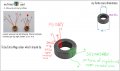
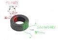
Here is my understanding so far:
q20221112 copy 1.jpg
 
Last edited:

sarahMCML

Joined May 11, 2019
703
This bifilar wire... is very new concept to me. I truly didnt expect to it. I learn something new then. I hope it will be the key.
I also checked this feritte core I have it's magnetism, by putting on a magent and checking if it sticks. And it does stick. Meaning it is feritte and not something else. Now Im checking it !!! Haha.
Here is my understanding so far:
View attachment 280432
Hi,

I've just built up Danko's circuit exactly as in post #57 using a 20mm green toroid core that I found. I used about 22 turns bifilar for each primary, and the same for the secondary but wound it over the top of the primary.
Powered from 5 volts, it takes 53mA and is supplying 3.3 volts into the 150 ohm resistor load on the output side, that's with a 10uF smoothing capacitor. It's a little spikey on the output, but I'm sure I can get rid of that later.
Must go now!
 

Thread Starter

q12x

Joined Sep 25, 2015
2,227
Thank you miss @sarahMCML ! Glad to see someone is getting some results... haha. Also please share a picture with your finished transformer. I want to see it. It is always good for me to have a reference. Im an artist and always using references, in any domain, in any circumstances ! Remember this little detail from your best friend mister Q12.
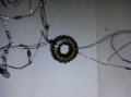
I just finished the primary as I understood it in my drawing. I used 2 wires (near eachother - not twisted) to form the bifilar wire, for the primary. I checked if my scrapped wire is making any shorts and is perfectly fine. I wired it very slowly and very carefully, very close to the core, but it is springy so... a bit is loose. But is close enough.
I made 26 turns primary with bifilar wire, because I had a slightly longer wire with each end already soldered.
It eat a lot of space from the core, almost half of it.
20221111_154025.jpg
 
Last edited:

Thread Starter

q12x

Joined Sep 25, 2015
2,227
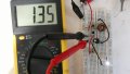
Aaand back to square 1 - I still used the same breadboard circuit as before. I obtained 1.35mA after the rectification.
I was curious if this bifilar wire will really have any effect compared to the previous windings. Not really... but is a bit more easy to make, I guess... 2 wires in the same time. Hmmm. I read is having some better properties but... im telling my observations so far. You get me.
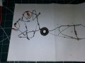
Primary bifilar wire = 26 turns
Secondary normal wire = 32 turns.
(as in my last drawing - as I understand it)
I will build mister Danko circuit next !
20221111_162534.jpg
 
Last edited:

sarahMCML

Joined May 11, 2019
703
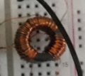
Here's a couple of pics of my setup. As you can see, the primary is wound all around the toroid, and was spaced out as evenly as I could get each pair, and then the secondary was wound over the top, equally spaced, but bringing it out at the opposite end for convenience. It's about 26 AWG wire by the way.
The other pic is of the circuit constructed "in the air", rather than on a breadboard.
One thing you should do is to use 1N4148 or Schottky diodes for your rectifier bridge, not the plastic module you're using at the moment. It's too slow for high frequency rectification use!


ToroidR.jpg


LashupR.jpg

I removed the power and scope leads from the above image to make it easier to see. The 10uF capacitor is off to the right.
 

MisterBill2

Joined Jan 23, 2018
28,011
Parallel wires wound next to each other is not the same as wires with at least 3 twists per inch. It is better than turns wound separately, but there is a significant difference. For winding a toroid where there is just a few feet of wire you could even use a twisted pair from a scrap of CAT5 cable. But that insulation does melt when it gets hot, so soldering will be tricky.
 

Thread Starter

q12x

Joined Sep 25, 2015
2,227
I just made a measurement of the resistance of the coils:
Untitled.jpg
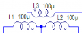
- From these R values, can you calculate how many Henry each side is?
Im not completely sure my coils are 100uH as yours !
1668205699616.pngI just made a fv reading of orig circuit, Ive also adapted it to my values:
I read from the (+) to collector top rail (A) and (+) to collector down rail (B)
1667901926350.png
I got 2 frequencies - most probably for the off and on state of the Tr.
For A: 7.4Hz and 7541Hz (7.4kHz)
For B: 7.3Hz and 7341Hz (7.3kHz)
 
Last edited:

Danko

Joined Nov 22, 2017
2,222
- From these R values, can you calculate how many Henry each side is?
Im not completely sure my coils are 100uH as yours !
I measured my height. It is 1.78m.
Can you calculate how many money are in my pocket?
Resistance and inductance are absolutely different parameters.
 

Thread Starter

q12x

Joined Sep 25, 2015
2,227
Hmmm, what I mean by that is if I even get close with my coil parametrs to your parameters you have in your circuit.
Nevermind then.
My question still remains the same: - How to increase the amperage in this secondary circuit ?
 
Last edited:

Danko

Joined Nov 22, 2017
2,222
Hmmm, what I mean by that is if I even get close with my coil parametrs to your parameters you have in your circuit.
Nevermind then.
My question still remains the same: - How to increase the amperage in this secondary circuit ?
Answer is:
One thing you should do is to use 1N4148 or Schottky diodes for your rectifier bridge, not the plastic module you're using at the moment. It's too slow for high frequency rectification use!
= = = = = = = = =
And download book: https://www.pdfdrive.com/electronics-all-in-one-for-dummies-d165779146.html
ADDED:
Pay attention on your circuit in #52
there are spikes 120V on collector (instead 40V max) and 70V on base (instead 6V max),
so that circuit is transistor's killer.
It can not work normally at all.
 
Last edited:

sarahMCML

Joined May 11, 2019
703
I did try a 100nF ceramic cap along with the electro when I tested my circuit: It did nothing to reduce the spikes, unfortunately!
My unit is oscillating at about 33khz. The efficiency though is pretty awful, about 37%.
I did manage to reduce the spikes on the output significantly by putting a snubber, consisting of a 180 ohm resistor in series with a 4700pF capacitor, between the collectors.
Using BAT46 Schottky diodes instead of 1N4148's for the bridge rectifier got me an extra 0.5V output.
 

panic mode

Joined Oct 10, 2011
5,175
Pay attention on your circuit in #52
there are spikes 120V on collector (instead 40V max) and 70V on base (instead 6V max),
so that circuit is transistor's killer.
It can not work normally at all.
bases need to be protected like in lower image in post #41
collector circuit can also be protected by pair of zeners or MOV
 

Thread Starter

q12x

Joined Sep 25, 2015
2,227
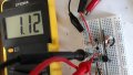
Haha, I tried @sarahMCML way of winding the coil
It matters a bit, and is a small difference between my way of winding and hers. The exact same wires used as before, but different position. Her way is Secondary on top of the Primary.
I may have some errors there as well, for example the large gap at some point between the windings.... it may be.... Also the paper isolator, may be thick enough to obstruct some of the electrical field...it may be....
I thought maybe the surface area where the winding is made is important.... hmmm
But the fact remains this: 1.12mA
20221112_151645.jpg
 

MisterBill2

Joined Jan 23, 2018
28,011
I suggest reducing the base drive by increasing the value of the two base resistors. try 2K ohm resistance if you only have 1K resistors on hand, or 2.2K (red,red,red, if you have them on hand. If that improves the efficiency a bit then try 4.7K resistors. The motivation for reducing base drive while still switching into saturation is to reduce the time in the linear mode coming out of saturation.
 

Thread Starter

q12x

Joined Sep 25, 2015
2,227
I tried that already. Really no significant change. But a good thought from you.
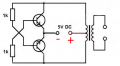
What I did today. I rewind back to this configuration :
1668268888921.pngsince it got me the best result and also is more safe from (possible) shortcuts.
I also made a LOT of changes in the secondary length of wire. I did a more detailed and serious list with values.
In the end I concluded I have 0.04mA on 1 turn.
I reached a maximum of 35turns with it's 1.35mA. Why maximum?
Because no matter how many turns I put on after 35, the amperage remains the same. 1.35 -1.30. It fluctuates but around this margin.
If I lower the turns number, 25,20,15,10, etc, I get a visible change in amperage.
All this experimentation lead me to the conclusion that the core itself is the limit I can go up in amperage. I knew this theory. But I didnt knew how much and all this data in reality. I believe is a fancy word for this, called permeability of the ferrite core. In a word, it means how much elecromagnetism can be milked from a specific area and shape of the used ferrite. In my case, a donut shape.
All this with 20turns as bifilar in the the Primary. And with @MisterBill2 circuit. At least, now I have a solid point of reference. I should have done it earlier, but... I didnt...
Like miss @sarahMCML did already, she used a very different core than mine, first of all bigger and more fat. And I bet the composition of it is very much different than mine. But we will never know that. All im doing is imagining. The point of it is what I should do next? My next idea is to change this core to one more similar to her. And repeat all this wiring again. And do all the experimentation, again.
Aaaah. We'll see.
 
Last edited:

sarahMCML

Joined May 11, 2019
703
Like miss @sarahMCML did already, she used a very different core than mine, first of all bigger and more fat. And I bet the composition of it is very much different than mine. But we will never know that. All im doing is imagining. The point of it is what I should do next? My next idea is to change this core to one more similar to her. And repeat all this wiring again. And do all the experimentation, again.
Aaaah. We'll see.

You are probably right about the toroids being totally different.
I modified my cct today by changing the 22K resistors to 3K9, and the snubber resistor to 33ohms.
With 5V input, it now gives 3.97V out at 66mA (97mA in), or 3.56V at 95mA (128mA in), 53% efficiency.
Frequency is now down to around 14KHz.

Please, before you re-build your circuit again, do try using some Schottky rectifiers rather than that small square one you have at the moment, it could make a big difference!
 
Top