An unusual error in my hacked DMM FS8233

BobTPH

Joined Jun 5, 2013
11,617
I know you guys repeated to change the diodes in the BR. Your mistake is not giving me a good reason why.
Sarah from post #68
One thing you should do is to use 1N4148 or Schottky diodes for your rectifier bridge, not the plastic module you're using at the moment. It's too slow for high frequency rectification use!
Stop blaming the people who are trying to help for your inability to read or comprehend what they clearly say. This is the second time you have dissed others with false claims. These people are trying to help, why they continue is beyond me.
 

Thread Starter

q12x

Joined Sep 25, 2015
2,227
Heh, that is not a blame. It is a suggestion. For better communication in the future.
You are very quick to draw conclusions. Not nice.
 

DickCappels

Joined Aug 21, 2008
10,662
To quote myself (some text removed for clarity) emphasis added for clarity:

One other thing, @sarahMCML noted that those bridge rectifier assemblies are too slow to use in switching power supplies and I think saw Danko mention the same. You would be much better off using four 1N916/1N914/1N4148 diodes or even better 1N60P, 1n5711, etc. The reverse recovery time (the time it takes the diode to turn on after being reverse biased) on those bridge rectifier modules is way too long for use in switching power supplies and may be contributing to your low output.
This discussion is moot because you already changed the diodes.
 

Thread Starter

q12x

Joined Sep 25, 2015
2,227
I think we can view this as progress.
Very true.
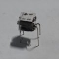
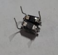
I think, some of you will appreciate how cute it looks:
There are 4 diodes stacked and hold by the solder and a bit of glue between them.
1668484688072.jpeg
20221115_053416.jpg
20221115_053319.jpg
(I really wish there was a better image arrangement system when posting images in the message window)
(For example these small square images can very well sit in line, and eat less vertical space, not in column as they are right now)
Sometimes I get lucky to put them in line. Just putting my idea on the table. User experience is never bad to get, right? Haha
 

sarahMCML

Joined May 11, 2019
703
Very true.
I think, some of you will appreciate how cute it looks:
There are 4 diodes stacked and hold by the solder and a bit of glue between them.
View attachment 280718
View attachment 280719
View attachment 280720
(I really wish there was a better image arrangement system when posting images in the message window)
(For example these small square images can very well sit in line, and eat less vertical space, not in column as they are right now)
Sometimes I get lucky to put them in line. Just putting my idea on the table. User experience is never bad to get, right? Haha
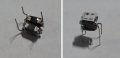
Using IrfanView, go to "Image" dropdown , then "Merge Images (Simple Panorama View" section. Select "Horizontal", add the File Names into the box, select a space between images if wanted (I used 20), "Space Colour", and finally, "Create Image".
Like this.

Merged.jpg

Done!
 

Thread Starter

q12x

Joined Sep 25, 2015
2,227
hahaha, yes, true hahaha
I was referring to the website and forum capabilities. My PS capabilities is totally other discussion. Hahaha.
Very cute @sarahMCML
 

Thread Starter

q12x

Joined Sep 25, 2015
2,227
Another update.
And from what I see, it should have been work... but it doesn't. -VERY strange !
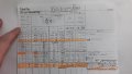
I compiled everything/every data I collected so far into 1sheet here. From 1 to 15.
16and 17 are the newest experiments I did today. But until 15, is everything I already did and in ascendent time order.
Everything in the LEFT side until the 3lines is for the PRIM. The bifilar and normal is for PRIM.
For the SEC, I only used 2 times bifilar, and the rest is normal winding. So those numbers in SEC this means.
For rapid view of the essential and the best results, I marked with Orange color these lines.
Please read these orange marked lines and compare between them and tell me your opinion. Why this DMM is still beeping from my last (17) experiment? It should have been worked. Im perplexed. - What's your 2cents thought might be ?
Thank you.
(if you dont understand something, ask me, and I shall respond on thee)
20221116_150016.jpgI actually did WAYmore tests than these here. But these notes are what remained behind.
 
Last edited:

sarahMCML

Joined May 11, 2019
703
Another update.
And from what I see, it should have been work... but it doesn't. -VERY strange !
I compiled everything/every data I collected so far into 1sheet here. From 1 to 15.
16and 17 are the newest experiments I did today. But until 15, is everything I already did and in ascendent time order.
Everything in the LEFT side until the 3lines is for the PRIM. The bifilar and normal is for PRIM.
For the SEC, I only used 2 times bifilar, and the rest is normal winding. So those numbers in SEC this means.
For rapid view of the essential and the best results, I marked with Orange color these lines.
Please read these orange marked lines and compare between them and tell me your opinion. Why this DMM is still beeping from my last (17) experiment? It should have been worked. Im perplexed. - What's your 2cents thought might be ?
Thank you.
(if you dont understand something, ask me, and I shall respond on thee)
View attachment 280818I actually did WAYmore tests than these here. But these notes are what remained behind.
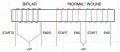
What you show as normal and bifilar windings in the upper left diagram of your chart are exactly the same, as long as you have The START of one winding connected to the END of the other winding for your middle common connection. If you don't then they oppose each other and you get the massive current consumption the you see in some of your tests.

Wiring.jpg

So, what EXACTLY are you getting in test 17. I'm still not quite clear from your chart? Why bifilar for the secondary? Is your wire very thin? And what do you mean by your DMM is beeping? maybe the battery is getting low?
 

Thread Starter

q12x

Joined Sep 25, 2015
2,227
What you show as normal and bifilar windings in the upper left diagram of your chart are exactly the same,
Can you be a bit more specific what "exactly the same" means to you? Or where do you see they are 'exactly the same' ?
Please clarify. You show me YOUR diagram being exactly with what I drew there. But you still tell me the ones I drew are 'the same'.
I sincerely don't get you.
And what do you mean by your DMM is beeping? maybe the battery is getting low?
I promised I will answer any questions.
That is exactly true, it is the warning this device is giving when the battery is low. Sign it is under powered. You guess it right. I already explained this behavior a couple of times until now. It's the only thing that is keeping me from advancing and finalizing this project.
Thank you.
 
Last edited:

DickCappels

Joined Aug 21, 2008
10,662
Not intending to be the master of the obvious, your meter is telling you that there is some voltage, but not quite enough. What if you eliminate the voltage regulator - would there then be enough voltage for your meter (without smoking it)?
 

sarahMCML

Joined May 11, 2019
703
Can you be a bit more specific what "exactly the same" means to you? Or where do you see they are 'exactly the same' ?
Please clarify. You show me YOUR diagram being exactly with what I drew there. But you still tell me the ones I drew are 'the same'.
I sincerely don't get you.

I promised I will answer any questions.
That is exactly true, it is the warning this device is giving when the battery is low. Sign it is under powered. You guess it right. I already explained this behavior a couple of times until now. It's the only thing that is keeping me from advancing and finalizing this project.
Thank you.
How you name the wires doesn't matter as long as they are phased correctly. So if you check the two drawings closely you will see that the ARE the same. Nothing there makes them either "normal" or "bifilar". They could be wound either way!
Your drawing showing the toroid shows the windings drawn as two separate ones, hence a "normally wound" one, like the right side one in my drawing.
I don't think you have wound your toroid as a bipolar one.
 

Thread Starter

q12x

Joined Sep 25, 2015
2,227
Not intending to be the master of the obvious, your meter is telling you that there is some voltage, but not quite enough. What if you eliminate the voltage regulator - would there then be enough voltage for your meter (without smoking it)?
- That's a good observation and I thought in the very beginning of it. Like you say, to supply with 3v directly, without the VReg in the middle. But in ALL my experiments, I had a wide range of voltages. Some were even fluctuating, not fixed. I omitted this detail to not overwhelm with too much information. So this VReg, for me, is playing a safety role, more than anything. It is guaranteeing me my device is getting 3V and no more than that. I know what you say, and I believe you are thinking on a normal transformer 240V to 3V with C-I iron core. That is stable and simple and direct. For some reason here in this situation, this small transformer is exactly like a paper boat on a wavy water in a bowl. Exactly ! In the sense that the wave that pass forward through it, is easily coming back with the same intensity. So.. it is waving back and forth. It is doing something, it is amplifying or transferring some sort of energy to the Sec, but.... it also letting pass back, the entire thing. All internally in its core, not really dependent of the circuit outside the Secondary. The SEC circuit is like a piece of paper glued with spit on it. Is powering it, but not really. Is only powering itself (the transformer), is doing its bizniz internally. The PRIMary is very important, it is dictating how many oscillations ad how hard to oscilate. The PRIM in my mind, is like the logic side of the circuit, it only oscillates. Doesn't matter how it does it, how complicated or simple the circuit is. When I drew that flip-flop circuit I didn't realized the coils in the Primary were influencing the oscillation of the PRIM circuit. That was my intention back then , to induce oscillations forcefully. But then I learn it is oscillating because those coils there. Very interesting circuit !!! Very simple to look at but extremely deceivable to how hard is to master it. A lot of traps and obstacles. So I had to figure out 'somehow' all this time, about this very strange phenomenon, for me at least. I learn quite a lot with this circuit here.
- All these are my personal observations ofcourse. Nothing here from what I say is text book, haha. So believe it or not, its up to you. But trust my detective Sherlokian nose, for getting very intim into things. Im not imagining, Im only observing and trying my best to figure out the cause and then find the solution. Thats my purpose with this circuit.
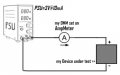
- I tested and observed something else today. When I power directly with 3V from my PSU, IT'S ampmeter is telling me 10mA (0.01A).
But I also hooked up a DMM set on ampmeter on the wire as well. This DMM is telling me 8mA-15mA fluctuating like 1 per second. I suppose its the display of the device that is changing data and that in turn is amperage changing. Also, because my PSU is also a SMPS, it is inducing some slight error reading when Im putting my hands on the wires of the probes ! Not as strong error as with my other way. My device under test, its screen is flickering visible ~1time/sec and it is not beeping. Sign that it is getting all the current it needs.
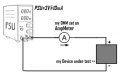
My very simple setup test:
1668659685614.png
Thats why I said earlier, this device should work already with the circuit I have !!!! This PSU test is proof of what it's maximum (15mA) is running at. Still very strange circuit ! But is good, because I learn something new.
Thank you !
 
Last edited:

Thread Starter

q12x

Joined Sep 25, 2015
2,227
I don't think you have wound your toroid as a bipolar one.
You have the right to believe what you want. I also believe I did it correctly. As an exercise in trust, you can repeat one of my many tests using the bifilar wires in the PRIM. Pick something in that list I made that has the less wires to put. You should get the same, or very close result& behaviour to what I have there. Depends on your surrounding circuit as well.
But for now, make a jump in your believe system by trusting me that I did it right. And continue from this point forward. To actually solve this problem. Hopefully.
You know I value all your opinions.
 

Thread Starter

q12x

Joined Sep 25, 2015
2,227
Let me clarify then, because this is a mountain of information and probably not as easy to read and understand.
I am very used to it but I can't expect someone else should fly easily through it. Right?
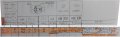
So we have this part here:
Screenshot_2.jpg
What this part is telling me?
Is telling me that for the last line (17) when I leave with no Load on the CD points, the SEC circuit is having 10V at AB points and 1.31mA. The PSU mA is staying at 40mA.
1668661599972.png
But when I insert a 100R Load at CD points, the same circuit in the SEC, is changed and is now 8.5V at AB points and 31.8mA.
The PSU mA is jumping to 100mA in this condition.
- So at this stage I know this SEC circuit can provide 3V at 30mA !!!! Correct? (If not, tell me why but it is my conclusion so far)
Next:
I hooked up my [device] to test. I power directly with 3V from my PSU, IT'S ampmeter is telling me 10mA (0.01A).
But I also hooked up a DMM set on ampmeter on the wire as well. This DMM is telling me 8mA-15mA fluctuating like 1 per second. I suppose its the display of the device that is changing data and that in turn is amperage changing. Also, because my PSU is also a SMPS, it is inducing some slight error reading when Im putting my hands on the wires of the probes ! Not as strong error as with my other way. My device under test, its screen is flickering visible ~1time/sec and it is not beeping. Sign that it is getting all the current it needs.
My direct setup test:
1668662081906.png
- At this stage I know the device is working fine with 3V@15mA. Correct?
Do you see what I did already until here?
My circuit in SEC is providing already 3V@30mA ! This device consumes and most importantly behaves normal with 3V@15mA. So I have double mA in my SEC circuit for this device to actually start work normally. But it is still beeping and not behaving.
Thats why I said earlier, this device should work already with the circuit I have !!!! This PSU test is proof of what it's maximum (15mA) is running at.
Im sure now is way more clear how I see the situation from where I stand.
Thank you for reading.
 

sarahMCML

Joined May 11, 2019
703
Let me clarify then, because this is a mountain of information and probably not as easy to read and understand.
I am very used to it but I can't expect someone else should fly easily through it. Right?
So we have this part here:
View attachment 280876
What this part is telling me?
Is telling me that for the last line (17) when I leave with no Load on the CD points, the SEC circuit is having 10V at AB points and 1.31mA. The PSU mA is staying at 40mA.
View attachment 280878
But when I insert a 100R Load at CD points, the same circuit in the SEC, is changed and is now 8.5V at AB points and 31.8mA.
The PSU mA is jumping to 100mA in this condition.
- So at this stage I know this SEC circuit can provide 3V at 30mA !!!! Correct? (If not, tell me why but it is my conclusion so far)
Next:
I hooked up my [device] to test. I power directly with 3V from my PSU, IT'S ampmeter is telling me 10mA (0.01A).
But I also hooked up a DMM set on ampmeter on the wire as well. This DMM is telling me 8mA-15mA fluctuating like 1 per second. I suppose its the display of the device that is changing data and that in turn is amperage changing. Also, because my PSU is also a SMPS, it is inducing some slight error reading when Im putting my hands on the wires of the probes ! Not as strong error as with my other way. My device under test, its screen is flickering visible ~1time/sec and it is not beeping. Sign that it is getting all the current it needs.
My direct setup test:
View attachment 280879
- At this stage I know the device is working fine with 3V@15mA. Correct?
Do you see what I did already until here?
My circuit in SEC is providing already 3V@30mA ! This device consumes and most importantly behaves normal with 3V@15mA. So I have double mA in my SEC circuit for this device to actually start work normally. But it is still beeping and not behaving.
Thats why I said earlier, this device should work already with the circuit I have !!!! This PSU test is proof of what it's maximum (15mA) is running at.
Im sure now is way more clear how I see the situation from where I stand.
Thank you for reading.
OK, we're getting somewhere now.
By my calculations, for the first part at 5V and 100mA, the circuit is taking 0.5W of power.
At points AB you have 8.5V and 31.8mA, which gives 0.27W output power, and:
At points CD you have 3V at 30mA with 100 Ohm load, which is 0.09W of power.
Since the AMS1117 is a Low Drop Out regulator, you could get away with reducing the number of turns on the secondary so that you only have around 5V at points AB. That way you wouldn't waste so much power in the regulator and take so much current in the primary.
You also don't appear to have any capacitors on the output side of the regulator. The AMS1117 can be particular on what value and type of caps it needs on both the input and output. See edit below.

In the second part, when you put your DMM into the circuit, what range do you have it set to? If it is set to a low milliamp range then what is probably happening is that it's internal shunt resistance, which is in series with the current going to your load, is affecting the operation of the circuit.
This is known as the "Burden Voltage" of the meter, and is present in all Current measuring ranges of meters. It differs between meters, and often needs to be taken into account, or worked around. One way of doing this is to put a low value known resistor in its place, say 1 Ohm, and then use a sensitive voltmeter to measure the voltage across it. From that you then work out the current running through it!
You could however try a large (say 220uF) capacitor across the supply after the DMM to smooth out the fluctuations.

EDIT: I just checked an AMS117 datasheet. It says that it is Very important that it has at least a 22uF tantalum capacitor on its output to maintain stability. If you don't have any, I'd suggest a 47uF Electro, plus a 0.1uF ceramic in series with a 1 Ohm resistor.
 
Last edited:

Thread Starter

q12x

Joined Sep 25, 2015
2,227
Thank you @sarahMCML !
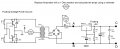
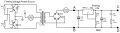
Is this what you say I should do?
I also just read the [Stability] section of the AMS1117 and also added the 10uF on the ADJ pin as well. Doing it by the book.
Floating voltage power source.jpg
 
Last edited:

sarahMCML

Joined May 11, 2019
703
Thank you @sarahMCML !
Is this what you say I should do?
I also just read the [Stability] section of the AMS1117 and also added the 10uF on the ADJ pin as well. Doing it by the book.
View attachment 280897
Yes, that's it exactly for the AMS117, but you still need the input capacitor across AB, as close as possible to the regulator.
As regards the resistor instead of multimeter for reading current thing, I really only meant that for when you were testing your 3V meter from your PSU. Your DMM current burden won't have much effect in the above circuit, because of the excess voltage that you have to play with!
 
Top