Why won't DPDT switch reverse a 2 wire reversible DC motor?

Thread Starter

DaleG

Joined Feb 11, 2015
6
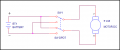
Have a 24V 5A 2 wire DC motor which, when hooked up to 24v 20A Sola power supply runs great forward and when I reverse wires to power supply terminals runs in reverse just as well.
Placed a 12v 30A DC DPDT maintained switch with power supply to the middle terminals, cross wired the corner terminals, and connected 2 end terminals to motor.
When switch is toggled to the left, motor pauses briefly then runs well. Then after toggling to maintained off, push toggle to the right and motor has a 3-4 second pause before it reverses direction or will stall and not turn at all.
Have a 9-60V 40A PWM ordered, wanting to install a power drive on a cross table. Thought this would be easy straight forward. Any help greatly appreciated.
 

tom_s

Joined Jun 27, 2014
288
a drawing/pic of how you have wired would be nice.

When switch is toggled to the left, motor pauses briefly then runs well. Then after toggling to maintained off, push toggle to the right and motor has a 3-4 second pause before it reverses direction or will stall and not turn at all.
this DPDT switch has centre off? (3 position) left / off / right?

most switches i've found are make-before-break - connect both sets of terminals before full switch deflection. not good in this scenario, you'de be needing a 'centre off' switch.
 

Dodgydave

Joined Jun 22, 2012
11,284
Your switch is rated at 12v, yet you're using 24v, i would use a DPDT relay put the motor to the wipers, and the supply to the crossed terminals.
 
Last edited:

Reloadron

Joined Jan 15, 2015
7,501
Either one of these two switch configurations should work:
Motor reverse A.pngMotor Reverse Switch.png

Since the motor manually runs fine in either direction the power supply is fine. While the switch is 12 volt rated @30Amp I don't see the 24 volts as a problem. The drawings are old and one reflects a 5V motor but matters not. It looks like you have a pause and are not changing motor direction without a pause as some SMPS power supplies really hate that. You do have a pause correct? Since you can manually run the motor fine in either direction less the switch and when the switch is added you have problems things seem to point to the switch and the stall maybe something the power supply dislikes. Can you measure the motor voltage when this happens as well as the supply, upstream from the switch? Measure on ether side of the switch in other words?

Ron
 

Attachments

Last edited:

Reloadron

Joined Jan 15, 2015
7,501
You might not.. but any safety/certification agency (UL,etc....) would :)
As Dodgydave suggested a relay (with appropriate rating) would be a better solution.
I agree on the relay but my understanding is this is just a temporary test scheme as there is a "9-60V 40A PWM" controller on order which I assume to be an H Bridge. That said and not knowing the switch contact ratings at 24 VDC verse 12 VDC I based what I said on most (and granted not all) DC switch contact ratings are bases on a range of for example 6 to 36 VDC, for example these common toggle switches. The original poster does mention a 24 Volt 5 Amp load which leaves a lot of room to derate the current going from 12 to 24 volts when at 12 volts the switch is rated for 30 Amps. So while I do agree a properly rated relay or H-Bridge is the proper solution for some general quick testing I figured the switch the original poster mentioned would do and should work. Without seeing the data sheet for the switch? No I would never suggest it as a permanent method to switch the motor current. Again, the original poster is waiting on the solution he plans to implement.

As to switches in general and AC verse DC switch contact ratings I like this read on the subject:
SWITCHES AC VS DC
by Art Bianconi (EAA 92330)
Technical Counselsor 1216
99 Dover Green
Staten Island, NY 10312

Some years ago I was fortunate to be able to work alongside engineers from
Underwriters Laboratories (UL) during destructive testing of electrical devices.
It was part of my apprenticeship as a designer for a major electrical manufacturer and it was during this period that I acquired an appreciation for the vital
differences between AC and DC ratings for switches.
I share this with you because I am growing increasingly concerned at the
widespread lack of appropriateness most aircraft builders demonstrate
when selecting switches for the cockpit environment. Each time a builder asks
me to perform a pre-FAA inspection of the aircraft, I carefully inspect the
switches and to date over three-fourths of the projects inspected have turned
up AC rated or non-rated switches in DC circuits.
There is a large scale misconception that any switch can be used so long as
its current rating exceeds the maximum load in the circuit. "Current is current;
what difference does it make whether it's DC or AC? Besides, I'm using a 125
volt AC switch in a circuit with only 12 volts!" The differences in load carrying
capability are dramatically non-linear and are best appreciated by carefully
inspecting a high-quality switch carrying both AC and DC ratings. Typical of this
is the roller and bar micro switch made by MICRO Corporation (Part No. DT-
2RV23-A7). Rated at 10 amps at 125 or 250 volts AC, the same switch can
only carry .3 (that's three-tenths!) of an amp at 125 volts DC. If DC voltage is
increased to 250 volts, the current rating drops even further to .15 amps! In
real terms, this represents less than 1/60 of the original load carrying ability
and all we did was go from 250 volts AC to 250 volts DC!
Those of you who can still remember the old Kettering coil ignition systems
will recall that when the condenser in the distributor went bad, the points
generally turned blue and melted down in just a few minutes. Cockpit switches
don't have the benefit of condensers to absorb the electrical inertia present in a
DC circuit and, as a result, the gap temperatures get hot enough to weld contacts,
even those made with exotic high temperature alloys.
The reason for this is simple enough to appreciate: because AC current
changes directions 120 times a second in a 60 cycle circuit; there are 120 times
when there is no current flowing at all. The current actually helps turn itself off
the moment it sees a gap and switch desrgners use this phenomenon to help
reduce the cost of manufacturing AC switches. In DC circuits, however, the
"push" is constant even when the points begin to open and the resulting arc is
DC current's way of demonstrating its resistance to termination.
"But won't my circuit breakers protect me?" No, they won't. Fuses and CB's
provide overload protection and a welded set of contacts will not, by themselves,
cause an increase in circuit load. Furthermore, what often happened during UL testing
was that the points welded shut making it impossibleto open the circuit. Cycling the switch
to the open position was often misleading — yes, the lever moved but inside
the switch, the cam had separated from the welded points and while it appeared
to have interrupted the circuit, the circuit was, in fact, still hot. If the circuit involved
was your fuel transfer pump or fuel boost pump and you thought it
turned off when in fact it was still running, what would the consequences
be? If it were a flap or elevator trim motor or a gear retraction device, how
would a tripped circuit breaker save you if the activating switch was welded
closed and in a mode other than what is required for a safe landing?
A DC rated switch will cost you about 3 times more than an AC rated switch
of identical current capacity. If your panel sports 10 switches (which is not
likely) the difference will be less than $35 (in 1986 dollars). You've gotten this
far. Is it worth jeopardizing your investment or your safety by cutting corners
with cheap or improperly rated switches.
 

ErnieM

Joined Apr 24, 2011
8,377
I agree on the relay but my understanding is this is just a temporary test scheme as there is a "9-60V 40A PWM" controller on order which I assume to be an H Bridge. That said and not knowing the switch contact ratings at 24 VDC verse 12 VDC I based what I said on most (and granted not all) DC switch contact ratings are bases on a range of for example 6 to 36 VDC, for example these common toggle switches. The original poster does mention a 24 Volt 5 Amp load which leaves a lot of room to derate the current going from 12 to 24 volts when at 12 volts the switch is rated for 30 Amps. So while I do agree a properly rated relay or H-Bridge is the proper solution for some general quick testing I figured the switch the original poster mentioned would do and should work. Without seeing the data sheet for the switch? No I would never suggest it as a permanent method to switch the motor current. Again, the original poster is waiting on the solution he plans to implement.

As to switches in general and AC verse DC switch contact ratings I like this read on the subject:
POTD (Post of the Day)
 

SgtWookie

Joined Jul 17, 2007
22,230
A single DPDT relay won't work for our OPs application, as the motor would run all the time either forward or reverse. They could use two SPDT relays, or an H-bridge type relay that is essentially two SPDT relays in one package. Don't assume that the PWM supply contains an H-bridge; I'm betting it does not. At this point, only the OP knows for certain.
 

Reloadron

Joined Jan 15, 2015
7,501
A single DPDT relay won't work for our OPs application, as the motor would run all the time either forward or reverse. They could use two SPDT relays, or an H-bridge type relay that is essentially two SPDT relays in one package. Don't assume that the PWM supply contains an H-bridge; I'm betting it does not. At this point, only the OP knows for certain.
Agree, maybe they will come back and share? :)

Nice Avatar there Marine.

Ron
 

Thread Starter

DaleG

Joined Feb 11, 2015
6
Thanks for taking time to help guys. My experience is limited and while trying self teach what appears to be straight forward obviously has underlying principles I have yet to understand.
My DPDT switch is 6 terminal (pin), 3 position toggle, on-off-on maintained (not momentary). Terminals are cross wired (1-6) and (3-4). Power supplied to middle terminals (2 , 5) with motor connected to end terminals (1 , 4) as per all of the diagrams I've seen on how to wire these switches. When switch is connected to power supply, terminals to motor (1 , 4) shows +24V with toggle to the left and -24V with toggle to the right. Appears to be reversing polarity as it should. Have not yet attempted to get readings when motor stalls, nervous when it happens because power supply starts making these clicking noises so immediately cut power. If anyone is familiar with power supply, Sola HD SDN 20-24-100C, it has LED diagnostic lights that according to the manual shows 'No DC' because the combination of a green and red light both light up when motor is hesitating or stalls completely. The clicking also coincides with LED,s turning off and on.

Attempted to buy 24VDC DPDT but only ones available have momentary on-off-on but can't find one with maintained 3 position toggle. That's why I bought the 12 VDC with heighest Amp rating (30A) I could find hoping it would work.
Have no experience with relays or H-bridges but will certainly learn about. Unsure of how to use relay to manually change rotation.

My plan was to connect Motor to DPDT to PWM to Power Supply. Unsure of specs for PWM, still waiting for it to arrive. Manufacturer says it is designed to control speed of DC motor and bought what appeared to have ample capacity for my motor. Again, what appears to be simple on paper.....
 

#12

Joined Nov 30, 2010
18,224
Important things:
1) Be sure the motor is at a complete stop before reversing the power.
2) Make sure you did not melt your switch before you learned about important thing number one.
 

Attachments

crutschow

Joined Mar 14, 2008
34,280
Either one of these two switch configurations should work:
.......................


Although the two circuits have an identical function, the circuit on the top can fail catastrophically under certain conditions.
For high current/voltage conditions with an inductive load, the arcing when the contacts open can cause an arc flashover (with lots of sparks) to the opposite terminal, which is at the opposite voltage, causing a short across the power.
Thus for any high power application, the bottom circuit is preferred.
 
Last edited:

Reloadron

Joined Jan 15, 2015
7,501


Although the two circuits have an identical function, the circuit on the top can fail catastrophically under certain conditions.
For high current/voltage conditions with an inductive load, the arcing when the contacts open can cause an arc flashover (with lots of sparks) to the opposite terminal, which is at the opposite voltage, causing a short across the power.
Thus for any high power application, the bottom circuit is preferred.
Absolutely! I tossed both cartoons out there merely as an example. When we get into DC motors that draw high current there are a number of considerations and rules to follow. What looks good on paper will not necessarily be the best solution. Also, not seen in these drawings is any over current protection, like a properly rated fuse.

Ron
 

MaxHeadRoom

Joined Jul 18, 2013
28,617
On a DC motor system that does not incorporate some kind of accelerated start, the maximum current can be obtained by measuring the armature resistance, don't bother reading the armature resistance with a Ohm meter, it is not as accurate as a current reading, done by locking the shaft and applying a small DC voltage while measuring the current, confirm the DC voltage and do the calc, move the armature to a couple of spots and take the lower reading.
Then use the reading together with the system voltage to calculate the max current.
Max.
 

Thread Starter

DaleG

Joined Feb 11, 2015
6
Thanks again for your all of your replies. With my limited experience I guess my most pressing question is why motor will run fine ( forward and reverse) when connected directly to power supply but has problems when I use DPDT switch.
As per my last post, with DPDT connected to power supply, meter shows +24VDC when toggle flipped to right and -24VDC when toggled to the left.
 

#12

Joined Nov 30, 2010
18,224
And, where did you measure? On the wires that go into the motor? If you can get the voltage there, the motor is bad. If not, you simply made a mistake.
 

Thread Starter

DaleG

Joined Feb 11, 2015
6
And, where did you measure? On the wires that go into the motor? If you can get the voltage there, the motor is bad. If not, you simply made a mistake.
With the DPDT switch wired as described in yesterday's post, connected DC power supply +\- to the middle terminals #2 and #5, crossed wired terminals (#1 to #6) and (#3 to #5) placed my red meter probe on terminal #1 and black probe on terminal #4. Without motor connected, pushed toggle from the middle (off ) position to the left and measured +24 VDC. Keeping the meter probes in contact with the same 2 terminals, pushed toggle back to off position and then to the right position meter measured -24 VDC. Does that show switch is reversing polarity thru those 2 terminals which are the 2 terminal which I attach to the motor ?
 

Denesius

Joined Feb 5, 2014
124
Thanks again for your all of your replies. With my limited experience I guess my most pressing question is why motor will run fine ( forward and reverse) when connected directly to power supply but has problems when I use DPDT switch.
As per my last post, with DPDT connected to power supply, meter shows +24VDC when toggle flipped to right and -24VDC when toggled to the left.
I remember I had an old DC motor that used stator windings instead of permanent magnets. If it was stopped, it would spin in one direction or the other based on the polarity of the power applied. But if it was turning in one direction faster than a few RPM, reversing the polarity didn't cause it to reverse, it just accelerated in whatever direction it was still rotating.
I wonder if your motor is the same thing. When you switch, are you allowing it to come to a stop? Try that & see if it works. If it does, your motor cannot be reversed while still spinning...
 
Top