 Facebook
 Google
 GitHub
 Linkedin
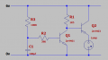
Can someone tell me what is going on here? i am trying to get my lamp to light slowly when i power up the circuit, my question is my lamp in the right place, should it be in the collector lead of Q2, is my transistor round the right way, which way does the current flow through Q2. i feel dumb because this is going to be an easy one for you bright people? I'm fairly new to electronics circuits.
My lamp doesn't light although i have a varying voltage at the collector of Q1
thanks.
My lamp doesn't light although i have a varying voltage at the collector of Q1
thanks.
Attachments
-
 8.4 KB Views: 53


