Why is voltage this way in this circuit and how to resolve it?

Thread Starter

hhsting

Joined Apr 25, 2024
395
Why this particular restriction on devices? Why no ICs?

How critical is the 0.5 V threshold? If it turns on and off at about 0.6 V or 0.7 V, is that close enough? If not, why not?

How much hysteresis do you need? Or is it okay for the LED to flicker as the solar panel output approaches the threshold?

What is the actual range of supply voltages that the circuit must operate over without modification?
It can be +_.1v. I want to learn how to build. Not much hysteresis
 

wraujr

Joined Jun 28, 2022
260
(1) You are using R6 and D5 to create a regulated voltage. BUT, this type of regulator can only supply small currents.
(2) You have two loads in your system, the small current load of your driver circuit AND your high current LED load (R4)
(3) You CAN"T get high current from your R6/D5 circuit.
A solution is to detach your R4 load from the D6/D5 supply and attach it to the +12V supply.
Once you do that R6/D5 can control your MOSFET gate requiring little current draw from R6/D5.
But, once your load is attached to 12V the ability t drive the LEDs and ability to handle varying input voltages becomes more difficult.

In other words R6/D5 is not a high current source and can't provide a regulated voltage to your load and its MOSFET driver
 

Thread Starter

hhsting

Joined Apr 25, 2024
395
(1) You are using R6 and D5 to create a regulated voltage. BUT, this type of regulator can only supply small currents.
(2) You have two loads in your system, the small current load of your driver circuit AND your high current LED load (R4)
(3) You CAN"T get high current from your R6/D5 circuit.
A solution is to detach your R4 load from the D6/D5 supply and attach it to the +12V supply.
Once you do that R6/D5 can control your MOSFET gate requiring little current draw from R6/D5.
But, once your load is attached to 12V the ability t drive the LEDs and ability to handle varying input voltages becomes more difficult.

In other words R6/D5 is not a high current source and can't provide a regulated voltage to your load and its MOSFET driver
Oh do you know of any circuit that can supply high current loads? Not ics, all in one chip but built from transistors capacitors resistor inductors diodes?
 

wraujr

Joined Jun 28, 2022
260

MisterBill2

Joined Jan 23, 2018
28,065
I suggest more study of DC circuit theory and voltage regulation principles. Seriously, understanding what one is trying to achieve is quite useful. Understanding the basic principle of zener diode voltage regulation would help a lot.
 

wraujr

Joined Jun 28, 2022
260
Welcome to experiment with this.
Change input from 21VDC to 12VDC
Change ZD1 to your desired voltage
Might have to tweak R1.
Could probably drop C2 move to output side.
1717612351238.png
 

LowQCab

Joined Nov 6, 2012
5,101
Here is a reasonably efficient way of Powering High-Power-LEDs .............
( But certainly not the cheapest way).

The LED will start to loose maximum-Light-Output somewhere below around ~6-Volts.
.
.
.
5A 60V Current Source .png
 

AnalogKid

Joined Aug 1, 2013
12,242
For a true, voltage-regulated output, I think the TL431 circuit from post #73, but with a darlington output stage as in post #86 is a good place to start. The 431 as an "adjustable zener "will improve regulation greatly.

If you want to do a regulated supply but with a straight zener diode (no ICs of any kind), that takes the #86 circuit plus two transistors and some resistors to form a differential pair. The circuit would be similar to post #55, but with an all-discrete amplifier. In this case you do not need D1 and D2 for temperature compensation; the diff amp takes care of that.

ak
 

Danko

Joined Nov 22, 2017
2,225
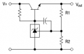
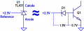
I studied but i dont understand how exactly circuit works to give stable voltage of 3 vdc.
Can you please explain in simple terms?
My English is zero, so see pictures.
1717643001464.png1717644526022.png
Capacitor eliminates possible oscillations. Try 10 nF.
Shift resistor (noname) value depends on V+, Vout, transistor B and Load current.
For V+ = 12 V, B = 40, Vout = 3 V, and Load current = 100 mA use shift resistor value 1 kΩ.
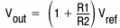
R1 = 10k, R2 calculates using formula:
1717644759235.png
===========
TL431 works like zener + transistor, but hundreds times accurately and thermostable.
Vref = 2.5 V.
ADDED:
What model transistor is typically used?
We already talked about transistor (TIP29C).
Also cant find LTspice model for TL431?
Download and install @Bordodynov's library: http://bordodynov.ltwiki.org/
ADDED:
What about if load current is 200mA? Also what about load current is 3A?
Answers are in electronics books.
Good luck, "Electrical Engineer".
 
Last edited:

WBahn

Joined Mar 31, 2012
33,079
What about if load current is 200mA? Also what about load current is 3A?
These are actually quite different operating regimes -- you are talking about a different of an order of magnitude, which often (not always) requires placing attention on different things -- or to at least start considering things that weren't much of an issue in the other regime.

It also depends on if you are talking about building a current source or a voltage source. You keep bouncing back and forth between them, which is why we strongly discourage covering multiple things in the same thread.

As has been stated numerous times, you need to decide what your requirements are -- what is it you NEED your circuit to do. Then decide on REASONABLE constraints regarding the operating conditions, such as supply voltage or output tolerance. Once you have that at least sketched out, you are in a position to start discussing reasonable circuit topologies and component selection.
 

Thread Starter

hhsting

Joined Apr 25, 2024
395
My English is zero, so see pictures.
View attachment 323943View attachment 323945
Capacitor eliminates possible oscillations. Try 10 nF.
Shift resistor (noname) value depends on V+, Vout, transistor B and Load current.
For V+ = 12 V, B = 40, Vout = 3 V, and Load current = 100 mA use shift resistor value 1 kΩ.
R1 = 10k, R2 calculates using formula:
View attachment 323946
===========
TL431 works like zener + transistor, but hundreds times accurately and thermostable.
Vref = 2.5 V.
ADDED:

We already talked about transistor (TIP29C).

Download and install @Bordodynov's library: http://bordodynov.ltwiki.org/
ADDED:

Answers are in electronics books.
Good luck, "Electrical Engineer".
I dont exactly see how you got the value for shift register (no name)?
 

thurtado

Joined Jun 6, 2017
12
Try using a pass xstr that uses the zener output at its base. Regulation wouldnt be great but you would no longer be starving the zener of current.
 

MrChips

Joined Oct 2, 2009
35,033
"pass xstr " is pass transistor.
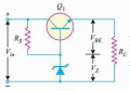
This is what he means. Q1 is the pass transistor. The output voltage is Vz + VBE.
1717869259158.png

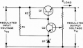
For adjustable output, you can use this.
1717869388127.png


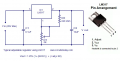
It is still easier to use LM317.
1717869470405.png
 

Thread Starter

hhsting

Joined Apr 25, 2024
395
What area of specialization, electrical engineer?? simple voltage regulators are covered fairly early in the engineering classes.
General electrical engineering. Had microelectronics so I know how transistor diodes work but all that was 30 years ago. Even still didnt go all that much into stable power supply and that much into how much you can build different circuits
 

dl324

Joined Mar 30, 2015
18,449
Any bjt that has hfe higher than 40??
Of course. Your options for 7A will be limited. Using a MOSFET was suggested in your other thread.

Instead of making us play guessing games, why don't you tell us what your complete specifications are?
 

Thread Starter

hhsting

Joined Apr 25, 2024
395
Of course. Your options for 7A will be limited. Using a MOSFET was suggested in your other thread.

Instead of making us play guessing games, why don't you tell us what your complete specifications are?
I did see other thread post #16
 
Top