Why is voltage this way in this circuit and how to resolve it?

If you want to supply a 3V led from 12V source effectively you certainly need a dc/dc converter.
Otherwise 3/4 of power will be waisted.

There is trick to use 3 leds (with less power rating) in series. In that case it can be considered as effective solution.

Zener itself can be used for very low power only (like 10mA) . It’s primary purpose is just to obtain reference voltage.
 

sarahMCML

Joined May 11, 2019
703
I dont have 3v reference. Their is nothing that can be done to correct situation current circuit with zener diode?
You would have to make R5 low enough to pass the 200mA that the load, R4, needs, plus the current that the rest of the circuit takes, plus some extra current through the Zener itself to bias it into a stable voltage point. The Zener would also have to be able to pass the whole current from R5 when the load was turned off!
R5 would have to be less than 45 Ohms, and 3W at least, and the Zener would need to be rated for at least 1W for safety!
 

Thread Starter

hhsting

Joined Apr 25, 2024
395
If you want to supply a 3V led from 12V source effectively you certainly need a dc/dc converter.
Otherwise 3/4 of power will be waisted.

There is trick to use 3 leds (with less power rating) in series. In that case it can be considered as effective solution.

Zener itself can be used for very low power only (like 10mA) . It’s primary purpose is just to obtain reference voltage.
My voltage varies from 3V to 12V its not just 12vdc. Their nothing one can do to correct the circuit zener didoe post #1?
 
My voltage varies from 3V to 12V its not just 12vdc. Their nothing one can do to correct the circuit zener didoe post #1?
It’s possible to make simple constant current regulator for Led, but as I mention when supply is at 12V it’s too lossy.
So it all depends whether effectivity is an issue.
 

Thread Starter

hhsting

Joined Apr 25, 2024
395
You would have to make R5 low enough to pass the 200mA that the load, R4, needs, plus the current that the rest of the circuit takes, plus some extra current through the Zener itself to bias it into a stable voltage point. The Zener would also have to be able to pass the whole current from R5 when the load was turned off!
R5 would have to be less than 45 Ohms, and 3W at least, and the Zener would need to be rated for at least 1W for safety!
But when voltage switches to 4V it goes down again to 1.4V

my voltage varies from 3v to 12v
 

MrChips

Joined Oct 2, 2009
35,030
The problem is not with the 3V supply. The problem is the 1Ω load.
Why are you using a 1Ω load? What exactly is the real load?
 

BobTPH

Joined Jun 5, 2013
11,618
Real load is 200ma led light for landscape at 3vdc. It cannot handle more than 3vdc or less.
Really? And you think you need a zener diode to set the voltage? In hundreds of circuits I have seen, not one used a zener diode in parallel to an LED. The resistor is enough to set the voltage.

1. You do not drive an LED with a voltage.

2. You do drive an LED with a current.

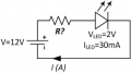
3. A higher voltage and a series resistor sets the current in an LED and provides negative feedback to keep it there. It is a current regulator.
 

Thread Starter

hhsting

Joined Apr 25, 2024
395
Really? And you think you need a zener diode to set the voltage? In hundreds of circuits I have seen, not one used a zener diode in parallel to an LED. The resistor is enough to set the voltage.

1. You do not drive an LED with a voltage.

2. You do drive an LED with a current.

3. A higher voltage and a series resistor sets the current in an LED and provides negative feedback to keep it there. It is a current regulator.
Step 3 can you elobrate about negative feedback loop? How?
 

BobTPH

Joined Jun 5, 2013
11,618
Step 3 can you elobrate about negative feedback loop? How?
Yes. If the current increases in the LED, due for instance to it heating up, the resistor drops more voltage, thus reducing the current.

It is a weak, but still effective form of negative feedback that prevents a runaway condition.
 

MrChips

Joined Oct 2, 2009
35,030
Understand the characteristics of an ideal constant voltage source and an ideal constant current source.
An ideal constant voltage source has zero source resistance. It can supply infinite amount of current.
An ideal constant current source has infinite source resistance. It can supply infinite voltage.

In other words, a constant current source starts out with a high voltage source and a series resistor. The higher the value the series resistance, the closer it becomes a constant current source.

1717425303943.png

In your case, if the source voltage is 12V, the series resistance required to deliver 200mA @ 3V is

(12V - 3V)/0.2A = 55Ω
 

Thread Starter

hhsting

Joined Apr 25, 2024
395
Your concept of how to drive an LED is wrong. Forget the constant voltage at 3VDC.
What you need is constant current at 200mA.

View attachment 323777
I need the constant vdc voltage because transistor mosfet and bjt turn the led lights on or off based in V2. If V2 is 0.5 vdc or below both transistors work together to turn on light.

I need something that doesn't use ics or if i can construct the ics using transistor resistor capacitor inductor etc therefore used zener diode to get constant 3vdc but that doesnt work with voltage source v1 varying from 3vdc to 12 vdc
 

Thread Starter

hhsting

Joined Apr 25, 2024
395
Understand the characteristics of an ideal constant voltage source and an ideal constant current source.
An ideal constant voltage source has zero source resistance. It can supply infinite amount of current.
An ideal constant current source has infinite source resistance. It can supply infinite voltage.

In other words, a constant current source starts out with a high voltage source and a series resistor. The higher the value the series resistance, the closer it becomes a constant current source.

View attachment 323778

In your case, if the source voltage is 12V, the series resistance required to deliver 200mA @ 3V is

(12V - 3V)/0.2A = 55Ω
See post #37
 

Thread Starter

hhsting

Joined Apr 25, 2024
395
What is your source that is supplying the initial voltage and current? Is it some form of Solar array?
So there are two voltage sources. V2 that varies from 2vdc to 0 vdc. V2 is coming from solar panel. V2 sets threshold voltage to turn transistors on or off

V1 voltage source varies from 3vdc to 12vdc and that is coming from 120vac standard 20A outlet plug that has transformer and converts to dc voltage.
 
Top