Why is voltage this way in this circuit and how to resolve it?

Danko

Joined Nov 22, 2017
2,224
Is the 3V, 7V and 10V load is where load is suppose to be attached? What is the circuit call? Also can you explain how the circuit works and how your getting resistor values?
Yes, 3 V Load1, 7 V Load2 and 10 V Load3 are your loads.

Minimal BF of TIP29C is 40, so for Ic=200 mA base current
should be more than 200/40=5 mA, therefore 1 kΩ value of resistor R1
is selected, which provides about 10 mA base current for Q2.

Circuit call is "Current stabilizer"

V forward of B-E Q1 is 720 mV, so value of R2 at desired current 200 mA
should be 720/200=3.6Ω.
 

Thread Starter

hhsting

Joined Apr 25, 2024
395
Yes, 3 V Load1, 7 V Load2 and 10 V Load3 are your loads.

Minimal BF of TIP29C is 40, so for Ic=200 mA base current
should be more than 200/40=5 mA, therefore 1 kΩ value of resistor R1
is selected, which provides about 10 mA base current for Q2.

Circuit call is "Current stabilizer"

V forward of B-E Q1 is 720 mV, so value of R2 at desired current 200 mA
should be 720/200=3.6Ω.
So I would get 12V at where you have :V load or I get 3V????
 

Danko

Joined Nov 22, 2017
2,224
So I would get 12V at where you have :V load or I get 3V????
When you deal with LEDs as load, forget about voltages!
Use only currents.
On your "3V, 200mA load" at current 200mA automatically will 3 V.
On your "7V, 200mA load" at current 200mA automatically will 7 V.
On your "xV, 200mA load" at current 200mA automatically will x V.
 
Last edited:

Thread Starter

hhsting

Joined Apr 25, 2024
395
When you deal with LEDs as load, forget about voltages!
Use only currents.
On your "3V, 200mA load" at current 200mA automatically will 3 V.
On your "7V, 200mA load" at current 200mA automatically will 7 V.
On your "xV, 200mA load" at current 200mA automatically will x V.
I want to make sire I am using below. I am using two in parallel so 200mA.

when I tirned my voltage to 12V it flicker on and off and then yellow part was damaged. So I dont see how led depend only on current?


Just found this amazing item on AliExpress. Check it out! $3.69 | 10pcs Edison Bulb LED Filament Lamp Parts 38mm DC3V DC12V LED Bead Incandescent Light Accessories Diode for holiday lighting DIY
https://a.aliexpress.com/_mLbjU34
 

Danko

Joined Nov 22, 2017
2,224
when I tirned my voltage to 12V it flicker on and off and then yellow part was damaged.
So I dont see how led depend only on current?
For LEDs:
Rule 1: Never put voltage on LED, only provide desired current through it.
Rule 2: Never connect LEDs in parallel, only connect them in series, if needed.
ADDED:
also I dont see any models TIP29C LTSpice. Where can I get one?
.MODEL TIP29C npn(IS=2.35E-18 NF=886M NR=886M RE=370M RC=1 RB=10 VAF=40 VAR=20 ISE=19.8F ISC=19.8F ISS=0 NE=1.5 NC=1.5 NS=1 BF=513 BR=5 IKF=195M IKR=195M CJC=131P CJE=131P CJS=0 VJC=515M VJE=515M VJS=750M MJC=330M MJE=330M MJS=0 TF=53.1N TR=6.9U EG=1.11 KF=0 AF=1)
ADDED:
I am using two in parallel so 200mA.
If you are using 100 mA LEDs, change value of R2, R4, R6 to 7.2 Ω.
 
Last edited:

dl324

Joined Mar 30, 2015
18,449
also I dont see any models TIP29C LTSpice. Where can I get one?
I think you're going to have issues if you use a power supply less than 12V. The power transistors will need a beta higher than 40.

The circuit I posted is more complex, but it will work with a supply of 5-12V.
 

Thread Starter

hhsting

Joined Apr 25, 2024
395
I think you're going to have issues if you use a power supply less than 12V. The power transistors will need a beta higher than 40.

The circuit I posted is more complex, but it will work with a supply of 5-12V.
Can you change R1 1k to 300 ohms and it should work for 3bdc to 12vdc in that circuit with beta of 40?
 

Thread Starter

hhsting

Joined Apr 25, 2024
395
For LEDs:
Rule 1: Never put voltage on LED, only provide desired current through it.
Rule 2: Never connect LEDs in parallel, only connect them in series, if needed.
ADDED:

.MODEL TIP29C npn(IS=2.35E-18 NF=886M NR=886M RE=370M RC=1 RB=10 VAF=40 VAR=20 ISE=19.8F ISC=19.8F ISS=0 NE=1.5 NC=1.5 NS=1 BF=513 BR=5 IKF=195M IKR=195M CJC=131P CJE=131P CJS=0 VJC=515M VJE=515M VJS=750M MJC=330M MJE=330M MJS=0 TF=53.1N TR=6.9U EG=1.11 KF=0 AF=1)
ADDED:

If you are using 100 mA LEDs, change value of R2, R4, R6 to 7.2 Ω.
I understand voltage is not consideration here but do you have some simple circuit for stable voltage as well?
 

WBahn

Joined Mar 31, 2012
33,076
I understand voltage is not consideration here but do you have some simple circuit for stable voltage as well?
The kind of circuit that would be reasonable depends on a number of factors, including what the voltage is, what the range of currents that must be supported, how stable it needs to be and over what conditions, as well as other factors like needed efficiency and size and cost constraints.
 

Thread Starter

hhsting

Joined Apr 25, 2024
395
The kind of circuit that would be reasonable depends on a number of factors, including what the voltage is, what the range of currents that must be supported, how stable it needs to be and over what conditions, as well as other factors like needed efficiency and size and cost constraints.
Ok i will just start new thread since in this circuit voltage is not an issue.
 

Danko

Joined Nov 22, 2017
2,224
I understand voltage is not consideration here but do you have some simple circuit for stable voltage as well?
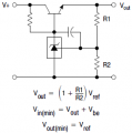
Simplest circuit:

1717468342005.png
TL431A: https://aliexpress.ru/item/10050055....productlist.search_results.15.50c966adxKLCwb
EDIT:
For what metric of "simplist"?
You are right. Sentence eliminated.
If Vin = Vout + Vbe, the circuit won't work -- where's the base current for the transistor coming from?
Ask authors of datasheet, please.
 

Attachments

Last edited:

Thread Starter

hhsting

Joined Apr 25, 2024
395
So, V1 does not vary from 3V to 12V. It is switch selectable from 3V to 12V.
Set the switch to 12V and you are done with that.
Use a 47Ω 1/2W resistor in series with the 200mA LED.
Its not that simple. I also then need transistor circuit which would turn off the current supply when I have solar panel voltage above 0.5vdc and turn on when I have 0.5vdc and below.
If i use what you said above then how can I build such transistor circuit without ics only using resistors inductors capacitors and transistors and diodes?
 

WBahn

Joined Mar 31, 2012
33,076
Its not that simple. I also then need transistor circuit which would turn off the current supply when I have solar panel voltage above 0.5vdc and turn on when I have 0.5vdc and below.
If i use what you said above then how can I build such transistor circuit without ics only using resistors inductors capacitors and transistors and diodes?
Why this particular restriction on devices? Why no ICs?

How critical is the 0.5 V threshold? If it turns on and off at about 0.6 V or 0.7 V, is that close enough? If not, why not?

How much hysteresis do you need? Or is it okay for the LED to flicker as the solar panel output approaches the threshold?

What is the actual range of supply voltages that the circuit must operate over without modification?
 

sarahMCML

Joined May 11, 2019
703
What is this "Landscape" thing you keep referring to, and what is its relationship to the varying different voltages (5V, 7V, etc)? We need a better explanation!
 
Top