 Facebook
 Google
 GitHub
 Linkedin
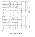
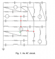
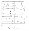
Below is the question given for the circuit. I am having trouble labeling the nodes so I can do a node analysis. Could someone explain how to label the nodes? A lot of them feel very ambiguous. Thank You
In the below circuit, the resistance of each resistor is 1 Ohm, the impedance of each capacitor is −j Ohm,
and the impedance of each inductor is j ohm, where j = √−1. The voltage phasor of the each source of
voltage is 10∠0◦ volts and electric current phasor of each source of current is 10∠0◦ amps. What is the
voltage magnitude of highest voltage magnitude node of the circuit?
Attachments
-
 56.1 KB Views: 30


")


