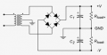
in a +12 -12 circuit, why is more voltage positive than negative?

Thread Starter

tsmspace

Joined Mar 16, 2026
82
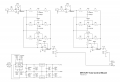
So, if I take a rectifier, I get 25v , then I put it to the L7812 and L7912 in a power circuit based almost exactly on the one in this audio circuit, (at the bottom, the separate signal flow with the +15 -15)

I get like 12v and -6. Why more positive voltage? why isn't it evenly divided? I'm sure it's not a particular component bad because i have more than one example and the behavior is consistent, where there is more positive voltage than negative voltage. I cannot, however, find any relevant discussions or explanations on it.
 

Attachments

Thread Starter

tsmspace

Joined Mar 16, 2026
82
Why are you using a polarized capacitor in the output filter of a circuit that has bipolar outputs?
well, that circuit is actually part of a kit you can buy that's an audio preamp ne5532 , and basically what I did was buy another kit, and take exactly those components (except I switched the L7815 and L7915 for the 12v counterparts) and put them onto a breadboard. So, I guess it was already in a design, which does work (although it too shows the uneven voltage distribution, I checked the kit. I do agree, though, that I need a higher input voltage to meet the +2-3 volts overhead each regulator calls for) ... I do know there are non-polarized capacitors but don't have any.
Check your pinouts. The 7812 and 7912 have different pin assignments.

Also, please post a link to the source of that schematic.

ak
I have double-triple-checked by now, having been first confused by how the LM7912 shares the pinout of the LM7812, while the L7912 does NOT share this pinout. As for the schematic source, man, I'm really sorry I don't have the source, someone posted it in a forum. They made the schematic based on basically the same kit I also purchased, it was a forum for where people discussed modding it because it had too much gain in the first stage, and this is definitely true, I also did the reduced gain mod and it is able to drive from headphone outputs now.

edit:::: I had posted the link to the source in another thread, so I found it, here it is: Ebay NE5532 pre amp tone control gain reduction | diyAudio


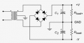
Are you using a center-tapped transformer?

View attachment 367809
I don't have one at present for 24v. I did order one but it's ordered from jameco which can take a while for transformers, since they list all the options that they can get but don't necessarily stock them. But, I didn't like any of the ones I saw on amazon and such since I really wanted to be specific, so I was fine with the lead time. Now however, I am without for the time being.

The transformer I'm using is one I took out of a rusty old cable-box adapter, it drives 24vdc onto a coax normally but i just alligator clipped onto the back of the rectifier, since it's using four regular diodes the leads are reachable with alligator clips. the board actually has the diodes and a cap on it so I can get the 24vdc also if I want. pretty useless overall since I keep buying so many little power supply kits but still cool. I did spend a good few minutes with a flashlight just trying to see if maybe there was a center-tap in there somewhere under some goo but there's only one on the primary side.

My question is, why is it always uneven in favor of the positive voltage?
 

Thread Starter

tsmspace

Joined Mar 16, 2026
82
So I think what's going on is that the L7812 has less resistance to ground than the L7912 , which results in more current flowing through the L7812 and therefore the center of the two voltages floats towards the negative side.
 

crutschow

Joined Mar 14, 2008
38,493
So I think what's going on is that the L7812 has less resistance to ground than the L7912 , which results in more current flowing through the L7812 and therefore the center of the two voltages floats towards the negative side.
Basically, yes.
Without the center-tap ground, the ground voltage will float to an arbitrary value depending upon the relative current loads in the circuit.

You could use a transformer without a center-tap to get both plus and minus voltages, but then each voltage would only be half-wave rectified.
 

Jon Chandler

Joined Jun 12, 2008
1,593
Somehow, the diagram disappeared in my post above, showing the proper connections for a bipolar supply.

The transformer must be center-tapped to provide 0 volt ground point.

clipboard_ec4c6199763edc96b7532422df1861e30.png
 

MisterBill2

Joined Jan 23, 2018
27,469
I see NOTHING WRONG with any of the power supply drawings posted!!
What may be a problem is the connections to those regulator ICs! AND i don't see the 0.1 MFD capacitors at the regulator terminals! My rather unhappy experience has been that without those caps the regulators can oscillate at some very high frequency (MHZ) and provide undesired outputs.
In addition, if the center tap connection of the transformer is not solid, all sorts of different results WILL ARISE. So aside from getting all of the connections in the correct places, adequate connectivity is required.
One issue that has been seen on this site, a while back, is the use of those imported clip leads, which seemed to have conductors of some very small wire. AND poor connections at the end clips.
 

Jon Chandler

Joined Jun 12, 2008
1,593
I see NOTHING WRONG with any of the power supply drawings posted!!
All caps and two exclamation marks?

You may not see anything wrong with the diagrams, but you made an assumption about the original diagram and missed a key point in response to my question:

I don't have one at present for 24v. I did order one but it's ordered from jameco which can take a while for transformers, since they list all the options that they can get but don't necessarily stock them. But, I didn't like any of the ones I saw on amazon and such since I really wanted to be specific, so I was fine with the lead time. Now however, I am without for the time being.
The "one" in question is a center-tapped transformer.
 

MisterBill2

Joined Jan 23, 2018
27,469
Without a center tapped transformer feeding that diode bridge circuit, it is a totally different system. For a low current supply feeding that preamplifier circuit, an alternative scheme will be to provide an "artificial ceter" with two 1K resistors in series across the transformer, the junction of the two then tied to that "ground" , serving to provide the center. THAT can work for a low current load. NO, it is not efficient, and it is only useful for light loads.
 

Thread Starter

tsmspace

Joined Mar 16, 2026
82
Without a center tapped transformer feeding that diode bridge circuit, it is a totally different system. For a low current supply feeding that preamplifier circuit, an alternative scheme will be to provide an "artificial ceter" with two 1K resistors in series across the transformer, the junction of the two then tied to that "ground" , serving to provide the center. THAT can work for a low current load. NO, it is not efficient, and it is only useful for light loads.
I had ordered a center tapped transformer, but thought they had not shipped it. Now I have checked the tracking and it was delivered but I never saw it,, porch pirated.
 
Top