How to get more bass from this eq circuit?

Thread Starter

tsmspace

Joined Mar 16, 2026
77
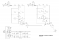
I have some of these modules, which are diy kits (some are self assembly, which is how I started getting them, but some are not available as self assembly, but offer the dc input i wanted) ,,, I found a schematic that looks to be right for one of them. The resistor values are different on the dc one, which is the one I'm using now, but otherwise I think the schematic is very similar.

I want to know if there is a way to get more bass out of it, or if not really. I have this other little amp to drive the same speaker cab , it only has treble and bass tone knobs, but does sound really mid-scooped, probably to eliminate hum, and although it has that familiar store stereo sound, the kit I have sounds much better for the speakers at least, although it does have a bit of hum at the moment. I do think the complete amp seems to have more bass clarity, and I'm wondering if some capacitor changes could give me a bit more from the equalizer.


Is this the wrong tree? I don't know anything about it all. This is the sale link for the one I want to modify, which is a different one from the schematic, but I do think the amplifier and eq have identical component layouts but with different resistor values to work with the dc vcc. Amazon.com: KIMISS Dual Channel Preamp Module for Audio Amplifier, 12V-24V DC NE5532 Tone Board, Hi-Fi Preamplifier with Low Noise & High Fidelity : Electronics

This schematic came from this thread here: Ebay NE5532 pre amp tone control gain reduction | diyAudio
 

Attachments

Irving

Joined Jan 30, 2016
5,104
It would be very easy to set this up in LTSpice and run a frequency sweep analysis to see the effect of each component. At the moment my best guess is that the 4u7 output capacitor and 10k volume control gives a 3dB roll-off at around 3.3Hz. The Bass pot is ineffective above approx 70Hz (3dB point)
 

Thread Starter

tsmspace

Joined Mar 16, 2026
77
It would be very easy to set this up in LTSpice and run a frequency sweep analysis to see the effect of each component. At the moment my best guess is that the 4u7 output capacitor and 10k volume control gives a 3dB roll-off at around 3.3Hz. The Bass pot is ineffective above approx 70Hz (3dB point)
never heard of it. I will look it up. technically I am only marginally certain that schematic is roughly accurate. I would have to try and follow the traces on the pcb, as I am unable to find the particular module schematic.
 

crutschow

Joined Mar 14, 2008
38,481
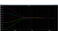
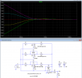
The top plot shows the original bass control-range.

The bottom plot shows the bass control-range with modified values for C3, R4, and R6, that gives a significant increase to the maximum bass boost:
1777833589230.png

1777836947506.png
 
Last edited:

Thread Starter

tsmspace

Joined Mar 16, 2026
77
So then I'm not going to argue this module is some finely tuned superior bit of engineering, it's a cheapy kit module from ebay/amazon, you can buy them for 10 bucks and I had to change the resistor from pint 1-2 and 6-7 just to give it an appropriate volume range, out of the box it's only good for a few notches before the gain blows itself out and the module just outputs distortion.

But, having said that, there are some things that tend to be simple "just do this it works all the time" kinds of things in electronics, and i am imagining that one of them is the capacitor values in a tone circuit, where people probably just use the same values all over the place in products in the same factories, resulting in a reasonable balance albiet with it's problems of no bass.

So if I move the bass "down the spectrum" as the chart shows, will there be a hole between the bass and mids, where these frequencies will make some kind of node that isn't really covered by the controls? Then I would end up with a band that is basically ignored, limiting the usefulness of the tone controls. As it is, I kind of imagine that although the spectrum could be wider, (which I suppose is the argument being 7-band eq), with the set up as it is, where the band is there is a nice coverage, while I would worry that were i to move the bass down, there would be less even coverage.

Of course I can easily swap out 2 resistors and a capacitor for each channel, but I cannot so easily add entire bands, so I am just wondering about this crossover.
 

crutschow

Joined Mar 14, 2008
38,481
o if I move the bass "down the spectrum" as the chart shows, will there be a hole between the bass and mids,
No.
If you notice the plot, the gain flattens to 0dB (gain of 1) at the mid to high frequencies, so the adjustment of the mid and high frequencies will be little affected.
 
Last edited:

Thread Starter

tsmspace

Joined Mar 16, 2026
77
No.
If you notice the plot, the gain flattens to 0dB (gain of 1) at the mid to high frequencies, so the adjustment of the mid and high frequencies will be little affected.
Ok. these boards are pretty cheap. So I'd ordered a spare and it has now arrived. First I will try to see if the schematic makes sense by trying to follow the traces, then I am probably going to try out the changes you posted if everything looks close enough. Then, I will have two separate boards to let me put them back and forth to see how I like them etc.


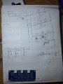
edit::: I've desoldered the board, and followed the traces for one side, both sides are identical. I double checked by counting total components, counting each component in the l signal path twice, and then totalling.

This image doesn't have all of the power traces, but all of the components of the signal path for the tone circuit should be present.

So I suppose the idea would be to make the 10k resistors either side of the potentiometer 5k, and then increase the value of the 223 caps off the bass wiper 443, and I would do roughly the same thing to the circuit that your other changes would? btw the 39k resistor across the first opamp is a 10k resistor on the one I'm using, which reduces the gain and gives me more range of motion on the volume without getting too loud too quickly (on my setup), which I learned from another forum post I found googling, to reduce the value of this output to input resistor to reduce the gain. This worked really well.
 

Attachments

Last edited:
Top