Psu design (biting off more than i can chew?) 240v - 3.3v 5v 12v and adj

Thread Starter

Antwan

Joined Mar 11, 2022
17
Hi all so litte back ground on the project.
i spent the last few years converting my house to cloud free iot devices and conrtols and became a little obbsed. I have I have used various of the shelf compents and buddled them in to project boxes or reflashed them etc to get the results i wanted but now im looking to build my first project board with all the intergration i need for aquariums, vivariums etc..

SOOOOO HEAR GOES!
starting with power and working forward in sections
I need line level coming in to the unit as it will be switching that to variuse outputs or a simple power brick would sufice hence why im asking for help.
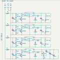
Im looking to use 4 Lm2596 ics for my 4 voltages i need but i need to feed them from 240v whats the best way in your opinion to bring the 240v down to say 24v at around 15A before hitting the next section of voltages.
 

ronsimpson

Joined Oct 7, 2019
4,645
Getting off the power line is hard, dangerous, (add more adjectives) I have done this for 45 years and it is not easy.
Purchase an off the shelf 240 to 24V 15A power supply.
A LM2596 little project is easy. You will not get killed when things go wrong. (and things might) I would get a 24V 1A current limited bench power supply to test the LM2596 boards on. When things go very wrong the little supply will not start a fire compared to the 300W supply.
 

schmitt trigger

Joined Jul 12, 2010
2,027
There are many ways to skin a cat. One of them, already proposed, is to get yourself an off the shelf 240VAC to 24VDC supply to feed all of your post regulators.
If you would like to build everything yourself, acquire a 240 to 18 VAC transformer, a bridge rectifier and a few thousand microfarads of bulk capacitance
 

Thread Starter

Antwan

Joined Mar 11, 2022
17
UPDATE

The end result is to be a fully developed for unit to be used in aquariums fishtanks etc i was trying to keep the device as clean and tidy a posible I work on primarly repairing large audio equipment so im no strager to high voltage. iv nevery really designed anything from pwer up before.

I am considering A 24v psu and taping the 240v of prior for now to simplify things but it would be nice to come up with a full custom pcb as I intend to do for each part and finaly a few custom boards with some ribbon cables with some luck

Any sugestions for safty protection would be great there i will be controling microcontrollers sensons relays switching 240v but ill share that as i get past section

Also is there a simple way to add a power good led to the output of the adjustable line i dont want it to be difrent dimming with the voltage i assume a constant current driver would do it but seams alot of extra parts for an led

Thanks for your advice so far
Ant
 

Attachments

schmitt trigger

Joined Jul 12, 2010
2,027
A Jfet works charms as a simple-as-peanuts, low-cost CC driver.
As long as you maintain a DS voltage above the pinchoff voltage, the led’s brightness will be constant.
 

Thread Starter

Antwan

Joined Mar 11, 2022
17
Who laser-cut you the front panel?
front panel im not passed the power supply yet i have a basic set up for what im trying to achive using som eproject boxes and din rail components and the concept works
needs some work on he software so it works stand alone so far home assistant is doing all the backend work for me
 

Thread Starter

Antwan

Joined Mar 11, 2022
17
A Jfet works charms as a simple-as-peanuts, low-cost CC driver.
As long as you maintain a DS voltage above the pinchoff voltage, the led’s brightness will be constant.
ahhhh didnt even think of that i saw the cc drivers cheap ill probably pick on up for testing and just steal the design if i cant fine one online then

but jfet seams simpler to impliment

Thanks again for all your help
im sure ill post again with updates when the parts arrive or on another thread with ideas for another part for i2c conrole for so 80v led grow lamps i use for the tanks :)
 

ronsimpson

Joined Oct 7, 2019
4,645
You could connect all the pin-5s together.
OR
You could have 10K on the top one, 11k on the next one and 12K on the next ....... This way each small supply will wake up slightly offset in time to reduce the startup stress on the 24V supply.
1769893979193.png
 

Thread Starter

Antwan

Joined Mar 11, 2022
17
You could connect all the pin-5s together.
OR
You could have 10K on the top one, 11k on the next one and 12K on the next ....... This way each small supply will wake up slightly offset in time to reduce the startup stress on the 24V supply.
View attachment 363001
great see this is what im looking for the best way to refine it i like the ide of less parts and the design is supposed to be able to pull a max of 12A but thats with all genuine parts and i doubt it will ever be close to that it was more to help a nice clean start up or maybe if i was to add the option for the micro to shut down the other voltages when not in use but that would add further complexatiy thats something for many revisions down the line I think.

Ill make the changes now and save a r1.2 :)

Thanks for yout input
 

Thread Starter

Antwan

Joined Mar 11, 2022
17
There are many ways to skin a cat. One of them, already proposed, is to get yourself an off the shelf 240VAC to 24VDC supply to feed all of your post regulators.
If you would like to build everything yourself, acquire a 240 to 18 VAC transformer, a bridge rectifier and a few thousand microfarads of bulk capacitance
was looking for something A little more safe and refind then that but thanks
 

Thread Starter

Antwan

Joined Mar 11, 2022
17
o
great see this is what im looking for the best way to refine it i like the ide of less parts and the design is supposed to be able to pull a max of 12A but thats with all genuine parts and i doubt it will ever be close to that it was more to help a nice clean start up or maybe if i was to add the option for the micro to shut down the other voltages when not in use but that would add further complexatiy thats something for many revisions down the line I think.

Ill make the changes now and save a r1.2 :)

Thanks for yout input
on the same note the original design called for a cap for each ic i wondering if one larger cap acrose the 24v line would do it maybe a small smd cap near each ic ksy to keep noise down. what do you think?
 

Thread Starter

Antwan

Joined Mar 11, 2022
17
to bulky for my needs the origle design im using for testing and development is using din rail mouted supplies im trying to shrink the unit down and increase reliability
oh i see whats happend i replied to a reply to you before haha sorry :)
 

Thread Starter

Antwan

Joined Mar 11, 2022
17
this is my first revistion using the sugested use case from TI who rate the chips at 3A a piece so nothing is set in stone its just basic function at this stage the zenor diodes in the under voltage protection are probrobably labled wrong also for the spec of each rail
 
Top