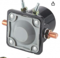
And now we're back to the diodes.Edit: Just realized there will be a delay needed so the direction relays don't release before the contactor opens, since that's when the major arcing occurs.
Is there something wrong with using four diodes (bridge) to suppress the contact arcing and increase their lifetime?And now we're back to the diodes.
YES!! There IS something wrong with protecting the contacts of a high current relay MADE TO NOT BE PROTECTED by diodes. First the load is a MOTOR, not an inductor. Second, a diode that would be suitable to absorb the energy from opening a circuit with about 50 amps flowing will cost a whole lot, (times 4), and third,the relay I suggested already has a double break contacts arrangement and a moving contact that is heavy. It weighs almost an ounce. (3cm diameter and at least 3mm thick!!Is there some wrong with using four diodes (bridge) to suppress the contact arcing and increase their lifetime?
Seems like low-cost protection to me.
What type of contact is MADE TO NOT BE PROTECTED by diodes?There IS something wrong with protecting the contacts of a high current relay MADE TO NOT BE PROTECTED by diodes.
I didn't know that.First the load is a MOTOR, not an inductor.
It doesn't have to absorb all the energy, it just carries the current for the short time it takes the motor stops.Second, a diode that would be suitable to absorb the energy from opening a circuit with about 50 amps flowing will cost a whole lot
So an expensive relay with large contacts is better than a cheaper relay protected by cheap diodes?the relay I suggested already has a double break contacts arrangement and a moving contact that is heavy.
The relay I suggested, the one being discussed, has been used by FORD to power the starter motor on a whole lot of their products, although I have not looked at any of the more recent ones. The starter motor is a very high current device and so that relay is intended to last thru thousands of starts with no problems. AND that relay design is also used in similar relays for other applications.What type if contact is MADE TO NOT BE PROTECTED by diodes?
I don't see how the diodes could possibly damage contacts, as they protect them from arcing.
I didn't know that.
But motors have inductance and will generate inductive type current until they stop.
It doesn't have to absorb all the energy, it just carries the current for the short time it takes the motor stops.
The rotational impedance of the motor absorbs most of the energy.
The bridge diode I posted in post #9 has a 300A surge rating, and costs less than U$3.
So an expensive relay with large contacts is better than a cheaper relay protected by cheap diodes?
Don't see how the small forward drop of a diode can strike an arc if the diodes were directly across the contacts.Even with a diode bridge, it could still strike an arc and destroy the relays.
And how would you provide the reversing signal to the motor which is now done by two SPDT relays?
THAT looks like what I was talking about!!
I've never really thought about the mechanism as to how it happened. I just know it did. The arc struck between the contacts that were trying to open. The whole relay lit up bright green and the entire moving contact burned away.Don't see how the small forward drop of a diode can strike an arc if the diodes were directly across the contacts.
Then I suspect the diodes weren't connected properly or were underrated, since it takes in the neighborhood of 30V to maintain an arc.I've never really thought about the mechanism as to how it happened. I just know it did. The arc struck between the contacts that were trying to open. The whole relay lit up bright green and the entire moving contact burned away.
If you consider the simplest version being an SPST relay supplying a motor with a diode across the motor, when the relay opens, the inductance of the motor requires that the current continues to flow, so the voltage at the motor terminal goes immediately to -0.6V. That puts V+0.6V across the opening contact (where V is the supply voltage). That might be enough to cause an arc, and obviously in the case I observed, it was enough to cause an arc.Don't see how the small forward drop of a diode can strike an arc if the diodes were directly across the contacts.
What was the supply voltage for when you got the arcing with a diode?That puts V+0.6V across the opening contact (where V is the supply voltage)
24V - which makes it rather more likely to happen than 12V.What was the supply voltage for when you got the arcing with a diode?