Need to calculate RC snubber for Relay Bounce in 170VDC Discharge Circuit

Thread Starter

RockPlanet25

Joined May 15, 2025
3
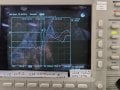
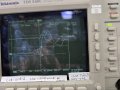
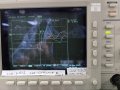
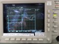
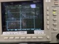
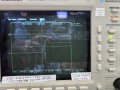
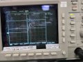
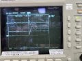
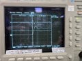
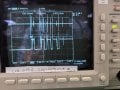
I have a contact bounce issue where a 170VDC voltage (rectified 120VAC) is being discharge into a 4K resistive load through a relay contacting circuit. The source power is from a charged 47uF polarized cap with a . The Relay contact bounce is causing high frequency noise transients to get into the system power and ground rails, specifically a 12VDC power circuit, and causing a DAQ to lose track of its internal state machine. The shortest transient is ~800ns wide but all rise times are typically about 400nS. During the contact spiking, the transients can reach upward of 300Volts. The entire bounce event time span varies between 5mS and 10mS. I would like to implement an RC snubber to help lower the spikes or soften the edges during the contact bounce events. Can anyone supply an equation to help choose these values?
Relay_Contact_Noise_170VDC.pngRelay_Contact_Noise_170VDC.png
 

schmitt trigger

Joined Jul 12, 2010
2,053
Capacitor manufacturer Cornell Dubilier has a very extensive application guide to calculate a snubbing circuit.
Search for it at CDE dot COM
 
Last edited:

crutschow

Joined Mar 14, 2008
38,392
It will be difficult to suppress the noise from the bouncing contact with an RC snubber.
Snubber circuits are normally used to suppress inductive ringing, which is different than noise from contact bounce.

Would be better to use a DC output solid-state-relay (SSR) since they have a fast response (≤10ms) and don't bounce (example).
 
Last edited:

Thread Starter

RockPlanet25

Joined May 15, 2025
3
Thanks for the suggestion. A solid-state system may be better, but the design is in place and works for 99% of the fixtures already constructed for 99% of the time. Changing the design would not be feasible, unfortunately.
I tried an RC snubber made of a series 10 ohm and 10nF capacitor and saw significant improvements in the coupled noise and relay bounce peak vales. The relay contact bounce peaks went from about 308Vpk spike (-27V undershoot) on the 170VDC throughput to about 280Vpk (-4V undershoot) with the snubber circuit across the in-to-out relay contacts. The coupled noise on the 12VDC system dropped from about +/-3.5V spike (these were separate polarity spikes inversely relative to the bounce polarity) to about +/-1.78V (this was a ringing noise instead of an inversely polarized spike). The rise times actually increased about 30nS with the snubber installed as noted above. It may be an incorrect assumption, but I think the reduction of energy transferred due to the snubber circuit effect was due to the systems "natural" low band-pass impedance blocking the higher rise time wave front, although the greater peak voltage certainly played a part in the larger energy transfer.
I have attached my scope captures for reference.
Any feedback is welcome.
 

Attachments

Thread Starter

RockPlanet25

Joined May 15, 2025
3
I found the CDE formulas and tried the calculations using the peak voltage on the VDC discharge bounce of 308V through 4K and got C = 6nF and R = 11.6 ohms. If I use the VDC value at first contact of 170V through 4K I got C = 2nF and R = 13..1 ohms. I plan to do some empirical experiments in these ranges to see what the best solution for the 12VDC rail noise transfer reduction is. This is pretty close to the values I used for my initial experiment with R = 10ohms and C = 4nF.
Thank you for your input!
 
Top