(Need Real-World RC values) Analog Automated Pump Controller for Utility company Water supply

Thread Starter

tejprn

Joined Mar 2, 2026
6
Hello Everyone,
I am not an electronics guy but building a simple project to detect water arrival in utility supply line, switch on the pump if tank isn't full, stop when either tank gets filled or water supply is stopped. Please ask any clarifying questions for details I have missed.

I need to know the REAL WORLD values of resistors (R1-4) and capacitors(C1-2) to get desired delay times. (S1-Relay60secs, S2-Buzzer15secs in ON state, Relay30secs in OFF state)
What type of resistor and capacitors would fit?

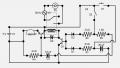
Attached is the circuit diagram with RC values and approx timings(VoltSIM simulator) for taken values.
(S1-Relay40secs, S2-Buzzer14secs/on+Relay28secs/off)

Key:
Cable - 2 pair Cat5e UTP(60ft)
Control circuit - 5v DC using a 1A phone charger
Relay - 30A 250V, coil 5v 180ma current
Load - 1hp pump on 230v 50Hz AC
S1 - push button micro limit spst pressure switch(NO) on pipe line before pump
S2 - 2 stainless steel probes(NO) inside pipe after pump
S3 - magnetic reed float switch(NC) inside tank overflow pipe

Working:
Pressure builds when water supply is released in pipes.
S3 NC indicates Tank not full.
S1 gets pushed.
C1 gets charged.
Q1 base gets current.
Rl0 activated.
Pump starts.
Pump sucks pressure within 2 secs.
C1 discharges for 40 secs.
Water reaches S2 by 40 secs.
S2 probes conduct.
C2 gets charged
Bz0 sounds water arrival alarm for 14 secs.
S2 continues conducting till water is supplied in pipes.
S3 disconnects when Tank gets filled
... OR ...
S2 disconnects when water supply gets over
C2 delays relay release for 28 secs

I need any expert advice if this will work in real world and what will be the exact resistor and capacitor values required.
I am not expecting the timings to change but for future upgrade, would it be better to use a small pot for adjustment or just use a higher time window beforehand.
I appreciate each one taking time to read this. ThanksAuto Motor Controller_v13(Off).png
 
Last edited:

MisterBill2

Joined Jan 23, 2018
27,159
The circuit is a bit complex, and while it is correct, it is a challenge to follow. The resistors used for timing seem to be lower values than the time claimed.

My understanding of the required function of the overall circuit is to monitor the level of water in a tank, and if the level is not high enough, to run the pump to fill the tank when water becomes available, and to stop the pump when the tank level is high enough. In addition, the pump must not run when there is no water available. That seems to mean that there must be a short delay after water pressure becomes available before the pump is started, AND that the pump must switch off if the water pressure drops excessively, as well as when the tank is full.

Please let me know if this description is correct, or if I have made an error in my understanding.
 

Thread Starter

tejprn

Joined Mar 2, 2026
6
The circuit is a bit complex, and while it is correct, it is a challenge to follow. The resistors used for timing seem to be lower values than the time claimed.

My understanding of the required function of the overall circuit is to monitor the level of water in a tank, and if the level is not high enough, to run the pump to fill the tank when water becomes available, and to stop the pump when the tank level is high enough. In addition, the pump must not run when there is no water available. That seems to mean that there must be a short delay after water pressure becomes available before the pump is started, AND that the pump must switch off if the water pressure drops excessively, as well as when the tank is full.

Please let me know if this description is correct, or if I have made an error in my understanding.
Yes Sir,
You are absolutely right on the timing. The time I got for these values of resistors and capacitors are in a simulator app called VoltSIM. I want to verify and get real values for my desired timings.

S3 - water level not high enough ~ tank is not full
You are right here.

But, my expectation is to start pump right away (no delay in starting) as soon as pressure is detected through S1 in the hope that water supply has started.
However, this attempt to pull water will be run for 60secs (preferred real world target time) and then C1 would be completely discharged saving the pump from dry run.

If water does get pulled uptill S2(ss probes), it sounds the alarm for 15secs (preferred) simulatenously running the relay as long as water is available.
Ultimately when the water does leave, C2 starts discharging and in about 30secs (preferred) the relay stops.
It's the same effect if S3 gets disconnected (opens when float switch rises due to tank level reaching highest point.)

I assume C1 - 2000uf, C2 - 1500uf might be what I need for those values of resistors for my real world timings.
Again, I don't know if this is right but it's very rough estimate.
 

MisterBill2

Joined Jan 23, 2018
27,159
It might be simpler to use another pressure switch on the discharge side of the pump to sense that iit still has the water supply present.
Evidently the piping arrangement is not so very simple as I had thought.
With some industrial pumping systems two pumps are used, the first pump being a centrifical type that is flooded by the liquid supply, and that pump feeds the positive displacement pump that provides the pressure. The low pressure from the first pump operates a second pressure switch to operate the higher pressure pump, which must not run dry or it will be damaged. The system is more complex, but it is very reliable and does not require any timers, only one pressure switch and one level switch.
 
Last edited:

crutschow

Joined Mar 14, 2008
38,316
That schematic is drawn in a manner not conducive to easy understanding, and the different color traces add to the difficulty.
Different colors are fine on a wiring diagram but not on a schematic.
 
Last edited:

MisterBill2

Joined Jan 23, 2018
27,159
For industrial pumping systems, where reliability is very important, timers are seldom part of the operation sequence. Pressure and float switches are used, and flow sensing switches may also be used.

Now I understand that the pump will need to provide suction to pull in the water from the source, which evidently is not a water well , although I have seen water wells that slowly fill so that the water must be pumped into a tank so that it is available when required.
I have been in cities that have different sections, with water supply available for only two hours in each section, so that every building must pump a day's required water into a tank during that two hour time. So I understand that it is veryimportant to sense correctly and immediately when the water becomes available, and to start pumping immediately, until the tank is filled.
It seems that the variables are the water pressure change when the water becomes available, as well as the time at which it becomes available.
 

dl324

Joined Mar 30, 2015
18,216
I need any expert advice if this will work in real world
It won't work well. You're depending on the base-emitter junction voltage for switching and that isn't a well-defined voltage. A voltage comparator would be a better choice.

As previously mentioned, the schematic is poorly drawn. The unnecessary connection dots are quite distracting. Not to mention the unnecessary colors and the dark background. And the flow is just awful.
 

Thread Starter

tejprn

Joined Mar 2, 2026
6
I am sorry for the poor drawing, but that's how the UI is on the app. I edited it in ms-paint, hope it's a bit more readable. Check attached image.
The dots are either joints or endpoints of components.
This is my first project for home use and not any for industrial use. The sensors will be placed on/in 1 inch pvc pipes.
Pressure is mostly in acceptable range to trigger the sensor, I want to manage the timing to have a fill.
I am ok even if it's not super-reliable. I am ready to accept a drift of 5-10 secs because of the transistor. I have a manual version of this running fine for the last 3 years but now I wanted to automate it to run without human intervention.
Would replacing the transistors with mosfets a good move?
 

Attachments

MisterBill2

Joined Jan 23, 2018
27,159
OK, now I understand that this is an existing system, with pipes and pump already installed and in place. And I see that adding a second pump is not an option. Now I understand that water must be pulled up-hill some distance to the pump, and if that is already working, then the pump must already be a positive displacement pump that can create a vacuum to draw the water uphill, because the pump is above the level of the water supply.

So now I offer two suggestions for the piping system: First, use an electronic probe sensor to detect that the water supply has become available. This would not be triggered by any rise in air pressure that might happen. The second suggestion is to add a check valve in the water supply pipe, close to the supply connection but past the water sensor location, so that the pump will not need to pull out the air before pumping water. THAT will allow more time to put water into the tank. Those changes will allow a simpler control scheme that will not require any timers except for the buzzer that announces that the tank is being filled.
 
Last edited:

Thread Starter

tejprn

Joined Mar 2, 2026
6
OK, now I understand that this is an existing system, with pipes and pump already installed and in place. And I see that adding a second pump is not an option. Now I understand that water must be pulled up-hill some distance to the pump, and if that is already working, then the pump must already be a positive displacement pump that can create a vacuum to draw the water uphill, because the pump is above the level of the water supply.

So now I offer two suggestions for the piping system: First, use an electronic probe sensor to detect that the water supply has become available. This would not be triggered by any rise in air pressure that might happen. The second suggestion is to add a check valve in the water supply pipe, close to the supply connection but past the water sensor location, so that the pump will not need to pull out the air before pumping water. THAT will allow more time to put water into the tank.
First of all, thanks for trying to understand this. I think I focused on other things while trying to keep the post length controlled.
Issue1: Water supply timings were not consistent and unknown in duration, frequency and time.
Issue2: Water may not reach my tank unless pumped in.
Issue3: Supply line is underground, so cannot go out of my premises to setup/modify the water line.

Solution1: Setup an alarm whenever water supply starts and ends.
Solution2: Instead of water sensor, deploy a pressure sensor (sensitive), giving me a headstart (40secs) even before actual water arrives. Relying on water sensor may not work as water doesn't reach the premises unless pumped in.
Solution3: Sensor to be tweaked for triggering only on right amount of pressure. At other times, when no supply is there, there is almost 0 extra pressure. The sensor has neither missed a single instance not given a false alarm in 3 years. It has been confirmed through other offline means.

The water sensor/probes after the pump serves 2 purpose. It proves actual water has arrived and confirms pump has pulled so must be working. This can be confirmed as working pump reduces pressure on the S1 sensor and in my current setup the pressure led turns off within 2 secs of switching on the pump.

I think I am happy with the plumbing, piping, motor and the way manual alarm is working. Only that this requires me to switch on/off the pump whenever it alerts me through the buzzer and leds.

I just want a relay to takeover and thus planned this circuit but I have no idea about real timings I will get from these resistors and capacitors and if there would be enough power to drive the relay. I think the logic of the circuit works, but it needs optimization.
 

dl324

Joined Mar 30, 2015
18,216
I am sorry for the poor drawing, but that's how the UI is on the app. I edited it in ms-paint, hope it's a bit more readable. Check attached image.
You clearly have the ability to rotate and flip components, so you can't blame the poor layout on the app.

With the addition of the humps, in some ways, it's even worse. The dots and humps style (thankfully) died out in the 1960's.

1772638156729.png
Drawn with an old version of Eagle. Printed to black and white PDF to avoid the silly colors it uses too...
 

Thread Starter

tejprn

Joined Mar 2, 2026
6
You clearly have the ability to rotate and flip components, so you can't blame the poor layout on the app.

With the addition of the humps, in some ways, it's even worse. The dots and humps style (thankfully) died out in the 1960's.

View attachment 364192
Drawn with an old version of Eagle. Printed to black and white PDF to avoid the silly colors it uses too...
Thanks for the layout. This would clarify a few things for others. I can understand the use of colors and unnecessary dots is distracting. Being a newbie, I think I need more exposure to the best practices of a neat circuit diagram. I have no idea what pros prefer regarding orientation so chose whatever appeared simple to me.

I know the values seem incorrect for the timings I am targeting. Shall I increase the resistor value or the capacitor or have a balance?
 

MisterBill2

Joined Jan 23, 2018
27,159
I am aware of the drawing software limitations, I do not complain about it now.
There is also a drawing style referred to as a "ladder listing", which contains all of the information but is much less like a wiring diagram, or a circuit schematic.
The LADDER LISTING format is primarily used to convey the function of the system forservice diagnostics. I suspect that the software used could also produce a ladder listing.
 

dl324

Joined Mar 30, 2015
18,216
I know the values seem incorrect for the timings I am targeting. Shall I increase the resistor value or the capacitor or have a balance?
I don't think the circuit can work.

To get 40 seconds, C1 would need to be something like 10,000uF. That's a big capacitor that will have a high tolerance (-20/+80%) and high leakage current. Depending on coil resistance, R1 likely can't be larger, and probably needs to be smaller.

You mentioned using a MOSFET earlier (note that it's all caps because it's an acronym). That wouldn't work. The threshold variation in MOSFETs is high and gate leakage current is quite low.
 

MisterBill2

Joined Jan 23, 2018
27,159
So now I am suggesting a scheme that would require only one timer, which would have the pump run for some length of time every time the supply pressure sensor switch closes, if the "Tank Full switch is not open because the tank is full.
The second pressure switch would be after the pump, on the pipe to the tank, but close to the pump, so that it will close when water starts flowing. IF that switch opens then the pump should stop,also, if the tank full switch opens, the pump should stop.
 

Thread Starter

tejprn

Joined Mar 2, 2026
6
So now I am suggesting a scheme that would require only one timer, which would have the pump run for some length of time every time the supply pressure sensor switch closes, if the "Tank Full switch is not open because the tank is full.
The second pressure switch would be after the pump, on the pipe to the tank, but close to the pump, so that it will close when water starts flowing. IF that switch opens then the pump should stop,also, if the tank full switch opens, the pump should stop.
Simpler is better but there are caveats. I have thought about those before. Let me post the questions or issue I faced.
1. On pressure increase, S1 alerts.
2. On pump start, pressure reduces, so S1 turns off within 2 secs.
3. Same as suggested, I set the S1 timer as 60 secs (fair buffer for 40sec actual time taken by water to reach the pump)
4. We cannot have a hard stop for S2 due to water movement, slushing, occasional air bubbles and pressure highs and lows during the duty cycle. Having no delay buffer would force the motor to start/stop rapidly.
5. If we keep the start only on S1, and stop only on S2/S3, in rare cases of very low pressures, S1 may not trigger but water could have reached S2.
 

MisterBill2

Joined Jan 23, 2018
27,159
OK, I see the problems. The pressure switch S2 will need to be close after the pump. And the water sensing electrodes need to be close to SW1, the first pressure switch, so that they trigger as soon as water starts to flow.
 
Last edited:
Top