What caused AC harmonics and why differential amplifier can't eliminate them?

Status
Not open for further replies.

Thread Starter

Secan

Joined Sep 20, 2024
205
An ungrounded screen can itself pick up noise.

View attachment 353794
Are you making use of the DRL signal to suppress interference?
What is the "screen" you mentioned that can be ungrounded? What is meaning of "screen"?

I don't know how to enable DRL. I just read about it a while ago. Maybe it is only present during impedance check?
 

MisterBill2

Joined Jan 23, 2018
27,749
In all of that "Happy Talk" about the capabilities of this package, I saw not one word about using a local connection to cancel common mode noise. NOR did I see any reference to filtering the signal. Besides that, there is no reference to common mode noise cancelling, which is vital.
 

Thread Starter

Secan

Joined Sep 20, 2024
205
Btw.. to those discussing with me. You kept treating the unit as having instrumentation amplifiers, it doesn't use these. It deducts the common mode noise via firmware or software. For example, if you say deduct the independent ADC 2 and ADC 3 (not time multiplexed). You will get both differential output (simply from for example 8-6=2 and even deduct common mode (simply because all differences will be deducted).

Some say the technique is prone to bad CMRR. Because If you want to have a common mode rejection of, say, 50 dB, the paths need to be gain matched to 0.03 dB. They said that's a lot easier to do on a single small piece of silicon vs two different signal chains with their Rs and Cs, ADC chips etc. or the multiple inputs may have slight variations in scaling going it. But someone said that " Note, you don't need to physically gain-match channels, you only need to match their gain calibrations. 1e-5 gain calibration accuracy is easily possible, and would give you something like 100-3= 97 dB CMRR "

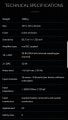
The ADC has sensitivity 85,7 nV / +/- 250 mV Amplifier type real DC coupled 16 × ADC 24 Bit (38.4 kHz internal sampling per channel)

Again it doesn't use any instrumentation amplifier or use any programmable gain amplifier before the ADC. The signal is mapped directly to the +/- 250mV range ADC such that if you have 10uV signal, It is mapped to the 10uV of the 250mV range.

Although I think it has amplifier of gain 1 only? If you will only use ADCs to deduct common mode.. what kind of amplifier do you need in front of it? I've been pondering this for a year but can't figure it out yet.
 

MisterBill2

Joined Jan 23, 2018
27,749
Deducting common mode noise in software is certainly an interesting theory. Also, not especially possible for all noise. Interfering signals may be fairly well reduced, but consider that the noise spectrum may not be exactly the same at both inputs, because of coming from different locations. So cancelling external noise in software is a false premise. Cancelling interfering SIGNALS is usually a different case.
 

Alec_t

Joined Sep 17, 2013
15,132
What is the "screen" you mentioned
I understood from your comment in post #59 that the input and output cables of the power supply are screened. If what is intended as a screen conductor is not at a fixed potential then, like any other conductor, it can pick up noise.
 

MisterBill2

Joined Jan 23, 2018
27,749
In the image of the external power supply that I saw, it is clear that the connection for the mains power feed includes the third pin for a safety ground. THIS DOES NOT MEAN THAT IT IS A SCREENED CABLE!! Only in rare instances are the power conductors shielded.
 

Thread Starter

Secan

Joined Sep 20, 2024
205
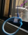
I did more careful tests. When I wear antistatic wrist band, the ripples are much stronger. My wrist bond is connected to the water tank that stands on the concrete (see pic below). Is the ripple stronger when I wear it because the long wires (about 10 meters) connected to the tank outside the window is serving as antenna or I am getting the AC frequency from the ground?

wrist band.jpg

Also the harmonics is much stronger when the electrodes are connected to my body. Can our body couple via capacitive coupling to the surrounding AC frequencies increasing the harmonics much bigger.
 

Alec_t

Joined Sep 17, 2013
15,132
Is the ripple stronger when I wear it because the long wires (about 10 meters) connected to the tank outside the window is serving as antenna or I am getting the AC frequency from the ground?
It could be either, since neither the wires nor tank have a low impedance path back to the mains power station. Your body also acts as an antenna.

For anyone following this thread, the manual for this amp is here.
It is stated on page 4 that "the potential equalization conductor should be connected to a potential equalization conductor of the room where g.USBamp is used", so clearly proper grounding is intended.

I'm not familiar with EEG equipment, but am confused by the fact that the electrode input groups include both 'reference' and 'ground' inputs. How do those differ? How (if at all) are they related to the 'potential equalisation conductor' ?
There is also a DRL terminal, which per page 22 is seemingly an output, but it is for internal use only. ????
 

Thread Starter

Secan

Joined Sep 20, 2024
205
It could be either, since neither the wires nor tank have a low impedance path back to the mains power station. Your body also acts as an antenna.

For anyone following this thread, the manual for this amp is here.
It is stated on page 4 that "the potential equalization conductor should be connected to a potential equalization conductor of the room where g.USBamp is used", so clearly proper grounding is intended.

I'm not familiar with EEG equipment, but am confused by the fact that the electrode input groups include both 'reference' and 'ground' inputs. How do those differ? How (if at all) are they related to the 'potential equalisation conductor' ?
There is also a DRL terminal, which per page 22 is seemingly an output, but it is for internal use only. ????
Reference is simply In-, the 4 socket is the In+. Ground is virtual ground. About potential equalisation conductor. Now i understand why it appears to be connector not connected inside the unit..i didnt know it was to be connected to ground in wall. You need to touch it before holding the electrodes.

The g.USBamp is used by most BCI (Brain Computer Interface) projects. It costs $17700 although i bought low price at ebay. You guys can build better than it. It is not truly instrumentation amplifier but just uses ADCs to subtract common mode by firmware and software.
 

MisterBill2

Joined Jan 23, 2018
27,749
Normally, voltages are measured relative to some other voltage, often on the "other side" of whatever is generating the voltage to be measured. What this system looks like is rather different from that normal scheme and it is causing problems for the TS. How could it possibly be otherwise???
I read thru that manual, and what is presented as information about the sensitivity DOES NOT COINCIDE WITH STANDARD PRACTICE or come even close.
The analog inputs are not described in a manner that provides useful information to a competent technical person,or an actual engineer.
There is no mention of the voltage range allowed, or the internal gain. There is no mention of the voltage per A/D converter scale factor or how it handles negative voltages.

And even on the multi-pin sockets, pin numbers are not given. Yes, the symbol for pin #1 is presented, BUT that is not adequate by any professional technical standard. In addition, no mention is made of the type or model number for the mating connectors. The amount of information and data that are not included is very large.

Even the power supply is an example of cost cutting. While it is claimed to be "a medical grade supply", all that means is that the leakage from the mains voltage to the output is very limited, meeting safety regulations. There is no mention of the noise level that is part of the DC output. Such a sensitive analog device should certainly be provided with a linear regulated and well filtered power source, because in this instance low noise matters more than maximum efficiency.
 

Thread Starter

Secan

Joined Sep 20, 2024
205
Normally, voltages are measured relative to some other voltage, often on the "other side" of whatever is generating the voltage to be measured. What this system looks like is rather different from that normal scheme and it is causing problems for the TS. How could it possibly be otherwise???
I read thru that manual, and what is presented as information about the sensitivity DOES NOT COINCIDE WITH STANDARD PRACTICE or come even close.
The analog inputs are not described in a manner that provides useful information to a competent technical person,or an actual engineer.
There is no mention of the voltage range allowed, or the internal gain. There is no mention of the voltage per A/D converter scale factor or how it handles negative voltages.

And even on the multi-pin sockets, pin numbers are not given. Yes, the symbol for pin #1 is presented, BUT that is not adequate by any professional technical standard. In addition, no mention is made of the type or model number for the mating connectors. The amount of information and data that are not included is very large.

Even the power supply is an example of cost cutting. While it is claimed to be "a medical grade supply", all that means is that the leakage from the mains voltage to the output is very limited, meeting safety regulations. There is no mention of the noise level that is part of the DC output. Such a sensitive analog device should certainly be provided with a linear regulated and well filtered power source, because in this instance low noise matters more than maximum efficiency.
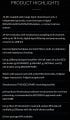
Below is more detailed description. BCI programmer told me it doesnt use amplifier with gain but only use 24 bit ADC to read microvolt for example and deduct by software akin to common mode rejection. What you think of this technique?

https://www.gtec.at/product/g-usbam...Z5qtSgGZ-e6vph414sKvocC9-npAIEN6BRpb9tIEWlQMd


20250808_043621.jpg
 
Last edited:

MrChips

Joined Oct 2, 2009
34,956
One problem I see is that multi-channel ADCs do not simultaneously sample all channels. The inputs are multiplexed and the ADC samples one channel at a time. This introduces two problems, (1) a delay between channels, and (2) cross interference when switching channels.

Thus when you compute the difference in software, you are not eliminating the true common mode noise.
Instrumentation amplifiers work by taking the true difference.
 

Thread Starter

Secan

Joined Sep 20, 2024
205
One problem I see is that multi-channel ADCs do not simultaneously sample all channels. The inputs are multiplexed and the ADC samples one channel at a time. This introduces two problems, (1) a delay between channels, and (2) cross interference when switching channels.

Thus when you compute the difference in software, you are not eliminating the true common mode noise.
Instrumentation amplifiers work by taking the true difference.
Its not multiplexed. The spec says: "24-bit resolution with simultaneous sampling of all channels with up to 38.4 kHz, digital signal filtering and preprocessing, connect via USB 2.0"

20250808_054626.jpg
 
Last edited:

MisterBill2

Joined Jan 23, 2018
27,749
One problem I see is that multi-channel ADCs do not simultaneously sample all channels. The inputs are multiplexed and the ADC samples one channel at a time. This introduces two problems, (1) a delay between channels, and (2) cross interference when switching channels.

Thus when you compute the difference in software, you are not eliminating the true common mode noise.
Instrumentation amplifiers work by taking the true difference.
In addition to what "Mr C" described, there is also the fact that after the conversion the data is sent over a serial link, sequentially, one channel at a time. So the data is always delayed a bit. So while the individual A/D channels are not multiplexed, there is no question but that the single serial data channel is shared between all of those channels. That may not be called "Multiplexed" but the effect is the same.
So it seems that the specification sheet author is indeed a master of "weasel words."

Then there is the claim alleging " BCI programmer told me it doesn't use amplifier with gain", and claiming the 1000 Gigohm input impedance. I think that BOB PEASE would rip them to shreds on that claim. The amplifier might possibly not have much voltage gain, but it must have some power gain to drive an A/D converter, because their input is not so high an impedance.

The result being that it seems to me that the TS got a much better price on ebay because the previous owner discovered that it would not work in their application.

It could possibly result in a solution if the TS were to explain just what the goal was that they hope to achieve, such as monitoring some body surface potential with some sort of software to observe some pattern of changes.
 
Last edited:

Thread Starter

Secan

Joined Sep 20, 2024
205
In addition to what "Mr C" described, there is also the fact that after the conversion the data is sent over a serial link, sequentially, one channel at a time. So the data is always delayed a bit. So while the individual A/D channels are not multiplexed, there is no question but that the single serial data channel is shared between all of those channels. That may not be called "Multiplexed" but the effect is the same.
So it seems that the specification sheet author is indeed a master of "weasel words."

Then there is the claim alleging " BCI programmer told me it doesn't use amplifier with gain", and claiming the 1000 Gigohm input impedance. I think that BOB PEASE would rip them to shreds on that claim. The amplifier might possibly not have much voltage gain, but it must have some power gain to drive an A/D converter, because their input is not so high an impedance.

The result being that it seems to me that the TS got a much better price on ebay because the previous owner discovered that it would not work in their application.

It could possibly result in a solution if the TS were to explain just what the goal was that they hope to achieve, such as monitoring some body surface potential with some sort of software to observe some pattern of changes.
If you will google "g.USBamp", you will find out almost all BCI (Brain Computer Interface groups in all universities and research centers use it. There is almost no subsitute because it has so many BCI software support like BCI2000, etc.. I'm learning BCI.

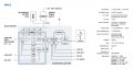
Something confuses me. In the following it has indeed an amplifier before the ADC. So the purpose is to have some power gain to drive an A/D? so the amplifier has the 1000 Gohm input impedance and possibly low output impedance to input into ADC? Why, can't an ADC have 1000 Gohm input impedance? If you will use ADC to map microvolt, what kind of amplifier preconditioning do you need to use to drive the ADC? So I can understand the purpose of the amplifiers before the ADC in the following g.USBamp specs diagram

eeg schematic.jpg
 

MisterBill2

Joined Jan 23, 2018
27,749
You need to read and understand the specifications of the A/D converter IC. You WILL NOT FIND THAT ON YOOTOOB. As for the one gig-ohm input impedance, that is not a believable number, based on the way the device is built.
And if other organizations are making the system work, probably they have an area for their research that has much cleaner power. AND a much lower level of ambient electrical noise on their power system. In addition, they probably have the connections made with careful attention to reducing the noise pickup.
 

Thread Starter

Secan

Joined Sep 20, 2024
205
If the mains input to the adapter has no grounding and the adapter input and output wiring is unscreened then there could be considerable mains supply noise in the vicinity of the amplifier. Since the amplifier input impedance is specified as >100 MegOhm the amplifier will be very sensitive to radiated mains interference if its inputs are not coupled to a much lower impedance. Even head impedance may not be low enough to reduce input noise to a non-noticeable level.
Different lengths and/or positioning of the input electrode wires will prevent complete interference cancellation by a differential amplifier.
Later I'll connect the ground of the AC adaptor to the tank outside (in the picture yesterday) using receptable with grounding. But since I don't have direct connection in the main panel to neutral in the transformer. The ground has to route via the tank, earth to the ground rod of the power pole and transformer. But because I don't fully insert big rods to the ground like in US grounding procedure. There would be resistance going under the earth to the power pole ground. How would this affect grounding?

To visualize better. Just imagine you remove the neutral in the United States power and just use the 2 hot wire connecting it to the AC adaptor. Because that is exactly what we have. The transformer neutral is tapped in middle so hot to neutral is 110V like in the United States.

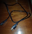
Can you pls share the photo of "screening"? to imagine what you mean the adaptor input and output wiring is screened? Did you mean coaxial cable? the input and output use normal rubber wire like used in the computer cord like the following (china made mass produced power cord, is it screened?) that I used with the AC adaptor to the EEG unit:


power cord.jpg
 

Thread Starter

Secan

Joined Sep 20, 2024
205
Later I'll connect the ground of the AC adaptor to the tank outside (in the picture yesterday) using receptable with grounding. But since I don't have direct connection in the main panel to neutral in the transformer. The ground has to route via the tank, earth to the ground rod of the power pole and transformer. But because I don't fully insert big rods to the ground like in US grounding procedure. There would be resistance going under the earth to the power pole ground. How would this affect grounding?

To visualize better. Just imagine you remove the neutral in the United States power and just use the 2 hot wire connecting it to the AC adaptor. Because that is exactly what we have. The transformer neutral is tapped in middle so hot to neutral is 110V like in the United States.

Can you pls share the photo of "screening"? to imagine what you mean the adaptor input and output wiring is screened? Did you mean coaxial cable? the input and output use normal rubber wire like used in the computer cord like the following (china made mass produced power cord, is it screened?) that I used with the AC adaptor to the EEG unit:


View attachment 353841
Just one question before I do the above. I measured between one leg of my 240V hot wire and metal tank the voltage 120V. In the United States, when you put multimeter probes between the hot leg and the appliance ground, do you also get 110V? or 0V? Just to be sure I don't miss something.

Also the transformer in power pole has the neutral grounded to make the primary not floating. Since it's already grounded at the power line, why do I have to ground the adaptor to avoid noise? The adaptor 2 hots are not floating anymore.
 

Thread Starter

Secan

Joined Sep 20, 2024
205
I connected the ground in the AC adaptor and the difference is like night and day.

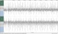
The following is WITHOUT ground connected to AC adaptor with all electrodes connected to my arm (EMG):

ac unground electrod on.JPG

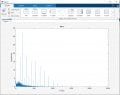
FFT of it:

ac_ungrounded_electrode on.JPG


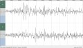
The following is WITH ground connected to AC adaptor with all electrodes connected to my arm (EMG).

ac ground electrod on.JPG

FFT of it:

ac_grounded_electrode on.JPG


Why does connecting the ground remove the huge amount of harmonics? What exactly occurs in the circuit??
 
Status
Not open for further replies.
Top