Why is that if the amplifier input impedance is specified as >100 MegOhm the amplifier will be very sensitive to radiated mains interference if its inputs are not coupled to a much lower impedance?? Please elaborate. Thank you.
Measuring biological signals is very challenging. You are trying to address many different obstacles.
Power supply noise is the least of your problems. You are surrounded by 60 Hz AC line interference.
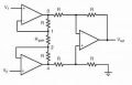
You need very high CMRR, common mode rejection ratio.
Measuring biological signals is very challenging. You are trying to address many different obstacles.
Power supply noise is the least of your problems. You are surrounded by 60 Hz AC line interference.
You need very high CMRR, common mode rejection ratio.
It may not use that. I don't know. The following is the spec of the g.USBamp (worth $17700 but I got only low price used but still I can't take chances to build 7.2V and bring down to 5V unless it is commercially available). It appears to use ADCs to cancel waveforms in different channels and there is calibration that uses gain and offset matching between channels:
"g.USBamp uses wide-range DC-coupled amplifier technology in combination with 24-bit sampling. The result is an input voltage range of +/- 250 mV with a resolution of < 85,7 nV! This means that any physiological signal can be recorded directly, without additional hardware. Neither high electrode offset voltage nor large artifacts resulting from electrical or magnetic stimulation will saturate the amplifier inputs. This feature is an important requisite for various artifact treatment and correction techniques. The use of digital filters avoids hardware-related variations between channels."
Hi Secan,
I am only suggesting you try the 7.2V 5V reg method in order to check IF the noise you are having problems with, is due to the Boost switcher.
It may not be the source of the problem.
Hi Secan,
I am only suggesting you try the 7.2V 5V reg method in order to check IF the noise you are having problems with, is due to the Boost switcher.
It may not be the source of the problem.
Is there a commercially available 7.2V to 5V clean regulator? Ill just buy one to try. Dont want to experiment building it bec it would take $4000 to repair the $17700 unit (see description in last message).
I think the TS's reply in post #8 (" When it is battery powered. There were no vertical lines.") is proof that it is use of the AC adapter which is the source of the problem.
So the simplest solution is to switch off and disconnect the adapter and use battery power only.
If I use battery, there are the ripples from the buck converter in the Powerbank (to boost 3.7V to 5V). If I use AC, there is 60Hz harmonic noise.
I just purchased it used at much lower price. I didn't buy it from the manufacturer so no support of any kind, and I'm not using it on anyone (not medical). I'm just learning to use it and my interests is FFT (Fast Fourier Transform) of frequencies at microvolt. But the noises of the AC adaptor and Powerbank is causing so many artifacts in the FFT so I want to understand what are the specific artifacts so I can either remove them or ignore them (if it wont' overlap the signal).
The vertical lines are obviously harmonics of the 60Hz. Googling I read they were caused by Fourier taylor series (?)
Anyway. Just this basic question first. If differential signal or ADC subtracts the common mode, how come the power source itself is not cancelled? for example if the voltage powering them is 5V, why is the 5V not considered common mode and cancelled?
Are you saying to achieve 3uV resolution. You should be able to acquire a current of V/R = 0.000001/100,000,000 = 0.03 picoA in the signal? Is 0.03picoA possible? What corresponding signal impedance is it?
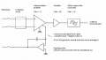
To recap. See illustration above. If the power supply has ripples at 7V. The ripples can also be deducted in the differential core even if it is not part of the input? If yes. Why cant it cancel the pure 7V DC power supply voltage turning it into 15V - 7V = 8V? I know this is a stupid question..but I need why it is stupid. Tnx.
I've been pondering the above this whole sunday and realised what you meant.
1. We don't measure skin current in EEG but voltage
2. So the 1nA you mentioned is not from the skin (I thought from the skin) but from the EMI interference inducing current in the electrode wire. Hence you need lowest source impedance. Ok got this if this is what you meant.
3. If one has active electrode which has electrode output impedance of just 10ohm to avoid attracting huge EMI interference. What is the use of electromagnetically shield room or faraday cage when you can just use active electrodes? Because I read some experiments done in faraday cages.
I've been pondering the above this whole sunday and realised what you meant.
1. We don't measure skin current in EEG but voltage
2. So the 1nA you mentioned is not from the skin (I thought from the skin) but from the EMI interference inducing current in the electrode wire. Hence you need lowest source impedance. Ok got this if this is what you meant.
3. If one has active electrode which has electrode output impedance of just 10ohm to avoid attracting huge EMI interference. What is the use of electromagnetically shield room or faraday cage when you can just use active electrodes? Because I read some experiments done in faraday cages.
Yes and no.
Biological electrical sources have very high source impedances. If the input impedance of the measuring instrument is low, you end up with a reduced voltage signal. You want the input impedance to be high to avoid the voltage divider effect.
The common mode signal is the unwanted interference picked up by the long leads of the EEG cables. This is eliminated or reduced by using an instrumentation amplifier with high CMRR (common mode rejection ratio).
Noise from the power supply is eliminated or reduced by choosing op amps with high PSRR (power supply rejection ratio).
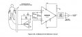
Since the EEG signals into the inputs are virtually floating, you need to reference them to a 0 V point. This is the purpose of the RIGHT LEG electrode.
Yes and no.
Biological electrical sources have very high source impedances. If the input impedance of the measuring instrument is low, you end up with a reduced voltage signal. You want the input impedance to be high to avoid the voltage divider effect.
The common mode signal is the unwanted interference picked up by the long leads of the EEG cables. This is eliminated or reduced by using an instrumentation amplifier with high CMRR (common mode rejection ratio).
Noise from the power supply is eliminated or reduced by choosing op amps with high PSRR (power supply rejection ratio).
Since the EEG signals into the inputs are virtually floating, you need to reference them to a 0 V point. This is the purpose of the RIGHT LEG electrode.
My g.USBamp has no RIGHT LEG (DRL) electrode. Instead you need to put the ground near yours ears with the bipolar pair in the head. I have the g.GAMMAbox active driver and active electrodes. The electrode has very high input impedance and only 10ohm output impedance so it attracts little interference in the wire. Also the g.USBamp doesn't use instrumental amplifier but 16 ADCs where they substract the common mode between ADCs (channels) by firmware or software. There is calibration by means of gain and offset mismatch equalizer between channels that takes care of any slight impedance etc mismatch between the ADCs.
Good to know your thesis is about EEG and FFT. But you probably used low pass filter of 100Hz. In my case. I need 1000Hz cutoff because my region of interest is not just the EEG bands but something more. This is the reason I need to eliminate or understand powerbank buck converter noise and AC adaptor noises as it affects within 1000Hz. Should I really need a faraday cage to eliminate the noise? But I can't afford it. What noise can be eliminated by Faraday cage (electromagnetically shield room) that the instrument can't do?
First: Where do the mains harmonics come from?? The harmonics are caused by non-linear load currents on the mains. The non-linear currents are caused by portions of the load that vary their effective resistance as the voltage changes. Mostly that is caused by diodes (rectifiers), but also by switching power supplies.
It is certainly possible to filter those lower frequencies out of DC power feeds, but it is not a trivial effort.
Harmonic energy picked up by sensor wiring can be greatly reduced by running both inputs very close to each other. This changes most of that picked up signal into a common mode signal, which can be rejected by a differential amplifier.It can also be rejected thru the use of a reference pickup, which will contain the common mode signal but not the differential signal. I recently underwent a "Major procedure", and the two ECG sensors on my chest had the reference pickup placed between them. Evidently it performed adequately.
But if the differential amplifiers or ADCs have CMRR that is very high. All the 60Hz interference can be cancelled, isn't it?
So the use of Faraday Cage is to substitute for high CMRR. I mean, without Faraday cage, you can duplicate all shielding by using batteries and very good CMRR equipment, is it not?
Please give example where only Faraday Cage can give result that can never be done even by the best instrumentation amplifier with best CMRR using the most noise free battery.

 Facebook
 Google
 GitHub
 Linkedin