What caused AC harmonics and why differential amplifier can't eliminate them?

Status
Not open for further replies.

Alec_t

Joined Sep 17, 2013
15,132
But if the differential amplifiers or ADCs have CMRR that is very high. All the 60Hz interference can be cancelled, isn't it?
From the traces you showed, it clearly isn't all cancelled. The notch filter seems to have suppressed the 60Hz fundamental somewhat, but its harmonics have not been cancelled so successfully, presumably because the noise is not the same in the two differential inputs.
 

rsjsouza

Joined Apr 21, 2014
429
What most folks here are talking about is PSRR, not CMRR. PSRR is the power supply rejection ratio and it ties well with your first spectrum - the first harmonics peak is 120Hz which ties well with the frequency of a full wave rectifier (as it was mentioned before). You need a good LDO voltage regulator with high PSRR to help you powering the system from the mains (more on PSRR).

When it is battery powered. There were no vertical lines. I know those vertical lines mean harmonics, but why aren't they cancelled? and what formed them? I once took a half course in electronics but moved to biology halfway. and so my idea of signal processing is only the Zilog Z80 microprocessor.
Moving on to the CMRR, this will be influenced by the common voltage difference between the inputs of the instrumentation amplifier. This is something mitigated by proper wiring on the input (shielded cables, twisted pairs, etc) and by fine tuning the input network of passive components/PCB/etc so they are as balanced as possible on each leg of the amplifier. This unbalanced input is probably reflected on the small 60Hz component seen in your spectrum figure, but also in part to the harmonics.

Enclosing your system in a shielded box (faraday cage) will prevent any irradiated 60Hz interference from reaching your system. However, the conducted 60Hz interference through the wires will still be present, unless the person/sensors/etc is also inside the box - something much harder to do.
 

Thread Starter

Secan

Joined Sep 20, 2024
205
First: Where do the mains harmonics come from?? The harmonics are caused by non-linear load currents on the mains. The non-linear currents are caused by portions of the load that vary their effective resistance as the voltage changes. Mostly that is caused by diodes (rectifiers), but also by switching power supplies.
It is certainly possible to filter those lower frequencies out of DC power feeds, but it is not a trivial effort.
Harmonic energy picked up by sensor wiring can be greatly reduced by running both inputs very close to each other. This changes most of that picked up signal into a common mode signal, which can be rejected by a differential amplifier.It can also be rejected thru the use of a reference pickup, which will contain the common mode signal but not the differential signal. I recently underwent a "Major procedure", and the two ECG sensors on my chest had the reference pickup placed between them. Evidently it performed adequately.
Is it not the harmonics are just vertical lines.. so can one just ignore them by just removing the vertical lines or would it impact the entire noise floor outside of the harmonics vertical frequencies?
 

MisterBill2

Joined Jan 23, 2018
27,748
OK, the problem is that what a perfect differential input can reject is common mode signals, that are the same amplitude on each input. BUT it can do that only within the linear input voltage range of the input.
BUT YOU DO HAVE A GOOD CLUE!!, which is that with battery power the signals do not appear!
THAT tells me that you need power supplies with increased isolation between the input and the output.

The bad news is that it might be as simple as disconnecting that ground pin on the power supply mains connection. Just use one of the adapters made for a grounding plug to use a two position outlet. A simple thing to try, easily reversible !

THAT was what it took to completely remove the mains frequency buzz for one church's sound system. It did not create a safety hazard for the reason that there was no grounded surface around for anybody using the sound system to contact and complete a shock circuit.
 

Thread Starter

Secan

Joined Sep 20, 2024
205
eeg screen1.PNG


eeg screen2.PNG


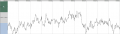
When I used battery. There is huge offset. In first image above the scale is 7.812mV from top to middle and -7.812mV from botttom to middle, the signal is offset by about 4.5mV. The bottom image is the autoscale showing the signal bigger at 4.5mV.

My questions:

If I used firmware setting high pass filter of say 5Hz to 250Hz. It can eliminate the offset. Does that mean it can eliminate the AC noise? Does AC noises simply cause offset that can be treated by using software high pass filter of 5Hz or above which can eliminate the DC bias. Or does AC noise mean the baseline shifts up and down 60times a second. But you can't see this shifting up and down 60times a second in the bottom image above, can you?
 

Thread Starter

Secan

Joined Sep 20, 2024
205
MrChips. Conventionally one needs to abrade the skin to have skin electrode impedance lower than 5kOhm. This is to avoid attracting EMI interference as the 5kOhm in the wire interacts with the interference EMI current producing huge voltage that can affect the EEG reading.

But if one uses active electrodes with buffer amplifier inside with big input impedance and only 10ohm of output impedance, then it is ok even if the skin electrode impedance is not abraded or 30kohm, 50kohm, 100kohm since the active electrode output impedance is only 10ohm so won't attract big EM current and voltage in the wire. All these assuming the EEG input impedance is greater than 100 Mohm.
 

MisterBill2

Joined Jan 23, 2018
27,748
Now a question: When you use an EEG system, do you know what you are looking for?? I am guessing some sort of pattern that has some repetition rate. Can the software filters be set to reduce, but not remove, other signal??
 

Thread Starter

Secan

Joined Sep 20, 2024
205
Now a question: When you use an EEG system, do you know what you are looking for?? I am guessing some sort of pattern that has some repetition rate. Can the software filters be set to reduce, but not remove, other signal??
I don't know. Only MrChips knows.

Anyway, what is the minimum microvolt voltage that can get swamped by AC interference? But even if it gets swamped, it is still on top of the baseline shift. For analogy. Imagine the signal as a boat. Even if the ocean rises, the boat stays afloat, so one can easily see it. So even with so many AC interference, is it not the signal is still there? And you can easily see it by FFT which separate the AC frequency and signal?
 

MisterBill2

Joined Jan 23, 2018
27,748
My reason for the question was to determine what frequency bands to not filter. Power harmonics have very definite and stable frequencies, so in theory it should be possible to remove the harmonics with software filters. Of course, that is not possible to do before the amplifiers boost the signal. That means that the amplifiers must be very linear , to avoid intermodulation distortion.
The big puzzle I see here is how do the power harmonics get into the input signal?? If the EEG input pickups are close to each other, and the reference pickup is near them, how does the harmonic voltage get in?? OR, is the reference connection connected also to the mains power "safety ground" by mistake. THAT connection would certainly introduce many unwanted signal voltages.
 

Thread Starter

Secan

Joined Sep 20, 2024
205
My reason for the question was to determine what frequency bands to not filter. Power harmonics have very definite and stable frequencies, so in theory it should be possible to remove the harmonics with software filters. Of course, that is not possible to do before the amplifiers boost the signal. That means that the amplifiers must be very linear , to avoid intermodulation distortion.
The big puzzle I see here is how do the power harmonics get into the input signal?? If the EEG input pickups are close to each other, and the reference pickup is near them, how does the harmonic voltage get in?? OR, is the reference connection connected also to the mains power "safety ground" by mistake. THAT connection would certainly introduce many unwanted signal voltages.
The adaptor is not connected to ground since we never use ground. The harmonics enter via the 2 hot wires (the only wires we have bec i have explained our electricians all come from the poorest so they cant differentiate between neutral and newton for example). The harmonics didnt enter via the inputs bec when I used powerbanks. They are gone replaced only by 250hz, 500hz, 750hz harmonics (what is the origin of these?)
 

Alec_t

Joined Sep 17, 2013
15,132
what is the origin of these?
What is the specified output voltage of the powerbank? If it's 5V, that is not an exact multiple of a lithium or NiMh cell voltage, so implicitly the powerbank includes buck or boost circuitry. That circuitry is likely the noise source.
 

MisterBill2

Joined Jan 23, 2018
27,748
If using batteries removed the noise frequencies, then the harmonics are entering thru the power supply connections. I see three possibilities: #1,The noise is created in the supply, #2, the noise is common-mode on the line and passes thru inadequate isolation between input and output of the supply as common mode noise on the DC power feed to the amplifier. #3, The noise is passing thru the input portion of the supply, including the transformer, and passing thru the regulator circuit which is not able to reject it.
I am guessing that it is either cause #2 or #3.
A quick check will be to operate the amplifiers on battery power, BUT with the supply common circuit connected to the amplifier power input common side. If it is still present then the cause is insufficient isolation and a common mode filter placed in series with both the positive and negative supply circuits should solve the problem. BUT the filter must have adequate current capacity to not approach magnetic saturation, because that will reduce the fitering ability.
 
Last edited:

Thread Starter

Secan

Joined Sep 20, 2024
205
If using batteries removed the noise frequencies, then the harmonics are entering thru the power supply connections. I see three possibilities: #1,The noise is created in the supply, #2, the noise is common-mode on the line and passes thru inadequate isolation between input and output of the supply as common mode noise on the DC power feed to the amplifier. #3, The noise is passing thru the input portion of the supply, including the transformer, and passing thru the regulator circuit which is not able to reject it.
I am guessing that it is either cause #2 or #3.
A quick check will be to operate the amplifiers on battery power, BUT with the supply common circuit connected to the amplifier power input common side. If it is still present then the cause is insufficient isolation and a common mode filter placed in series with both the positive and negative supply circuits should solve the problem. BUT the filter must have adequate current capacity to not approach magnetic saturation, because that will reduce the fitering ability.
You mean I must cut the following supply and route the supply common circuit connected to the amplifier power input common side? I can't cut it because it would damage it. Also I don't think the amplifier inputs can tolerate 5V voltage since the supply is also 5V. Isn't it common mode voltage is always lower than the supply voltage? And if harmonic is still present, you mean I must open the $17700 amplifier and put common mode filter inside the positive and negative supply circuits? It can ruin the unit and it has no warrantee.

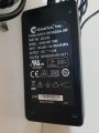
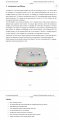
globtek ac  adaptor.jpg

Btw.. I can't find specification sheet for this Globtek GTM21097-3005 in Globtek website because it was discontinued item a few years ago. Do you know where to seek spec sheet for it?
 

Thread Starter

Secan

Joined Sep 20, 2024
205
What is the specified output voltage of the powerbank? If it's 5V, that is not an exact multiple of a lithium or NiMh cell voltage, so implicitly the powerbank includes buck or boost circuitry. That circuitry is likely the noise source.
(Misterbill2, don't miss the above message because whenever I wrote 2 messages consecutively, the first one is always missed)

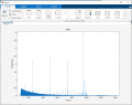
Alec_t, the following is the FFT of the harmonics from the powerbank at 250Hz, 500Hz, 750Hz. I tried 2 powerbanks and same harmonics that is not present when AC adaptor used (since AC harmonics is multiple of 60Hz). Since all powerbank use 3.6V or 3.7V and buck or boost circuity, can you please use oscilloscope on your powerbank to see what kind of ripples there is. My pocket oscilloscope (Fnirst DSO-TC3) is defective.

eeg_powerbank noise .PNG
 

MisterBill2

Joined Jan 23, 2018
27,748
You mean I must cut the following supply and route the supply common circuit connected to the amplifier power input common side? I can't cut it because it would damage it. Also I don't think the amplifier inputs can tolerate 5V voltage since the supply is also 5V. Isn't it common mode voltage is always lower than the supply voltage? And if harmonic is still present, you mean I must open the $17700 amplifier and put common mode filter inside the positive and negative supply circuits? It can ruin the unit and it has no warrantee. There is probably no room for an adequate common mode fiolter inside that amplifier enclosure. So the filter will need to be in a separate enclosure, so that the plug from the present supply can instead connect to the filter and the the output connection from the filter will connect to the amplifier. An in-line common mode filter is not a tiny package at all,

View attachment 353771

Btw.. I can't find specification sheet for this Globtek GTM21097-3005 in Globtek website because it was discontinued item a few years ago. Do you know where to seek spec sheet for it?
NO!!! I did not mean to cut the wires. IF, AS ON ALL DECENT COAXIAL PLUGS, THE OUTSIDE IS NEGATIVE, then just a clip lead to the outside barrel, and the other end of the clip lead to some point at the negative battery circuit. (AMPLIFIERGROUND.)
 
Last edited:

Thread Starter

Secan

Joined Sep 20, 2024
205
If using batteries removed the noise frequencies, then the harmonics are entering thru the power supply connections. I see three possibilities: #1,The noise is created in the supply, #2, the noise is common-mode on the line and passes thru inadequate isolation between input and output of the supply as common mode noise on the DC power feed to the amplifier. #3, The noise is passing thru the input portion of the supply, including the transformer, and passing thru the regulator circuit which is not able to reject it.
I am guessing that it is either cause #2 or #3.


Let me go back to your earlier message, to be sure it was understood well.

"#1, The noise is created in the supply:"

Did you mean from the power company or the adaptor?

"#2, the noise is common-mode on the line and passes thru inadequate isolation between input and output of the supply as common mode noise on the DC power feed to the amplifier."

My source is only 2 hot wires giving 220V. It is not 220V to ground but measures 110V from hot to neutral like in the United States. See youtube below (I can get 110V if I pressed harder or more water). Only we never have neutral supplied to us. Did you mean by common-mode there is harmonics in each 110V to neutral? So my 220V harmonics came from them? What do you mean by inadequate isolation? What is supposed to be adequate isolation?


"#3, The noise is passing thru the input portion of the supply, including the transformer, and passing thru the regulator circuit which is not able to reject it."

How does this differs to case #2 since it also passes by the input portion of the supply? you mean not common-mode?

A quick check will be to operate the amplifiers on battery power, BUT with the supply common circuit connected to the amplifier power input common side. If it is still present then the cause is insufficient isolation and a common mode filter placed in series with both the positive and negative supply circuits should solve the problem. BUT the filter must have adequate current capacity to not approach magnetic saturation, because that will reduce the fitering ability.
Last message you wrote: " NO!!! I did not mean to cut the wires. IF, AS ON ALL DECENT COAXIAL PLUGS, THE OUTSIDE IS NEGATIVE, then just a clip lead to the outside barrel, and the other end of the clip lead to some point at the negative battery circuit. (AMPLIFIERGROUND.) "

We are supposed to connect the negative of the battery plug to the amplifier negative supply line. Why do you mean above about connecting the plug negative to the amplifier negative. isn't this what we do? Also you mean in quote I must connect the AC adaptor output to the amplifier input with batteries being used? Can it take 5V DC from the adaptor? Isn't it common mode voltage is supposed to be lower than supply voltage (less than 5V)?
 

MisterBill2

Joined Jan 23, 2018
27,748
Let me go back to your earlier message, to be sure it was understood well.

"#1, The noise is created in the supply:"

Did you mean from the power company or the adaptor?

"#2, the noise is common-mode on the line and passes thru inadequate isolation between input and output of the supply as common mode noise on the DC power feed to the amplifier."

My source is only 2 hot wires giving 220V. It is not 220V to ground but measures 110V from hot to neutral like in the United States. See youtube below (I can get 110V if I pressed harder or more water). Only we never have neutral supplied to us. Did you mean by common-mode there is harmonics in each 110V to neutral? So my 220V harmonics came from them? What do you mean by inadequate isolation? What is supposed to be adequate isolation?


"#3, The noise is passing thru the input portion of the supply, including the transformer, and passing thru the regulator circuit which is not able to reject it."

How does this differs to case #2 since it also passes by the input portion of the supply? you mean not common-mode?


Last message you wrote: " NO!!! I did not mean to cut the wires. IF, AS ON ALL DECENT COAXIAL PLUGS, THE OUTSIDE IS NEGATIVE, then just a clip lead to the outside barrel, and the other end of the clip lead to some point at the negative battery circuit. (AMPLIFIERGROUND.) "

We are supposed to connect the negative of the battery plug to the amplifier negative supply line. Why do you mean above about connecting the plug negative to the amplifier negative. isn't this what we do? Also you mean in quote I must connect the AC adaptor output to the amplifier input with batteries being used? Can it take 5V DC from the adaptor? Isn't it common mode voltage is supposed to be lower than supply voltage (less than 5V)?
OK, there is obviously a serious communications problem here!! DO NOT CUT ANYTHING!!!

Understand that just because you do not have a "ground" connection for your mains power does not mean that there is not common mode noise on both of the mains supply lines that your external supply connects to.

In addition, it is also possible that the external power supply is the source of the noise, and that the supply is producing the noise. BUT IT IS ALSO POSSIBLE that noise on your mains power supply is passing thru that external power supply.

The fact that you do not have the noise when operating on internal battery power shows that the noise is entering thru the external power connection.
 
Last edited:

Thread Starter

Secan

Joined Sep 20, 2024
205
If the mains input to the adapter has no grounding and the adapter input and output wiring is unscreened then there could be considerable mains supply noise in the vicinity of the amplifier. Since the amplifier input impedance is specified as >100 MegOhm the amplifier will be very sensitive to radiated mains interference if its inputs are not coupled to a much lower impedance. Even head impedance may not be low enough to reduce input noise to a non-noticeable level.
Different lengths and/or positioning of the input electrode wires will prevent complete interference cancellation by a differential amplifier.
Alec_t, you mentioned if the adaptor has no grounding, it can cause noise. But if the input and output wiring is screened, it can't cause noise even if there is no grounding? Because there is so much noise in my EEG signal when using AC adaptor without ground connected. I don't know how to connect the ground because we never use ground.

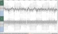
The following is an EEG signal I just tried the other day. The top is one bipolar or channel 1 minus channel 2. The channel 2 is the raw without differential input rejection. Btw.. I'm just learning to use EEG and the inputs are of course connected to the EEG inputs (see bottom).

ac noises.JPG


intro usbamp.jpg
 
Last edited:
Status
Not open for further replies.
Top