Delaying relay activation caused by sudden voltage changes in voltage stabilizer

Thread Starter

raming2024

Joined Jul 23, 2024
6
Hi,

I have an old analog refrigerator voltage stabilizer which uses relay system to stabilize voltage. It uses LM339 to compare sample voltages with a reference voltage to activate the relays. The mains voltage is 220 and the first relay gets activated around 200 volts.

My problem is when the mains voltage is e.g., 210 and I turn on a split air conditioner I get a sudden drop in mains voltage and a momentary relay click (on and then off) before the voltage is restored to its stable level.

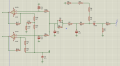
To solve this problem and to delay the activation of the relay for seconds, I placed a capacitor connecting the input sample voltage of LM339 to the ground. Below is the partial schematic of the sample voltage circuit. I placed C4 and C3 in the inputs of the comparator to block sudden voltage drops. Pin 6 (which activates relay1 at 200 volts) and pin 4 (which activates relay2 at 180 volts) are sample voltage inputs which are compared to their reference voltages (not included in the schematic) to activate the relays. After placing the capacitors in the inputs I tested the device and the result seems OK: I no longer get momentary relay on-and-offs when some high wattage appliances are turned on.

My question is if it is a good idea to place capacitors C4 and C3 to control the sudden voltage changes. I am concerned with the stability of the control circuit in the long run: specifically, could these capacitors leak voltage in the long run so that the sample voltage would need tuning? Do you recommend having these capacitors in the inputs given the problem I described? I am new to electronics and would appreciate any feedback about this idea.
 

Attachments

crutschow

Joined Mar 14, 2008
38,322
The schematic appears to show the same signal going to both inputs to the comparator which, I assume, is not correct (?).

If I could see the complete comparator circuit, I can give a better opinion as to whether the added capacitors would be a problem.
 

LowQCab

Joined Nov 6, 2012
5,101
Delaying the Relay's activation could easily allow the Refrigerator-Compressor to stop,
which would then require a Compressor-re-start under full Head-Pressure,
which usually just results in an even bigger Voltage-Drop, and the
Compressor Short-Cycling on the built-in Thermal-Overload-Switch until the Pressures come down.

This is not a good plan.

The correct way to fix this problem is to provide a separate Circuit for the Refrigerator,
and a separate Circuit for the Air-Conditioner.
.
.
.
 

crutschow

Joined Mar 14, 2008
38,322
Delaying the Relay's activation could easily allow the Refrigerator-Compressor to stop,
I doubt that the short time for the reduction in voltage due to the AC starting would easily cause the Refrigerator-Compressor to stop.

The TS stated that the delay modification works.
He just wants to know if there's anything wrong with the way he did it.
 

Thread Starter

raming2024

Joined Jul 23, 2024
6
The schematic appears to show the same signal going to both inputs to the comparator which, I assume, is not correct (?).

If I could see the complete comparator circuit, I can give a better opinion as to whether the added capacitors would be a problem.
Yes, the same signal goes to pins 4 and 6 but their reference voltages are different. I updated the schematic and added the reference voltages which are regulated by a 5.1 v Zener. I also simulated the pins 4 and 6 voltage-time relationship both when C3 and C4 are present and when they are absent in the circuit. It can be seen in the graph that when C3 and C4 are present in the circuit and the stabilizer is turned on, it takes 4-5 seconds for the sample inputs to reach their full voltage.
(Outputs 1 and 2 of the comparators go to the relay transistors and also provide feedback to the positive inputs as shown in the schematic.)
 

Attachments

MisterBill2

Joined Jan 23, 2018
27,186
The solution depends a whole lot on what the purpose of the relay voltage stabilizer. The quick fix will be to slow it's response so that it does not respond to the very short term voltage drop.
If the voltage is 210 and starting the AC unit drops it to 190 for two seconds while the compressor is running, it will probably keep running and not have a problem. And if it is not running then no problem. so the solution will be to slow the response of the LM339.

The part of the LM339 circuit that we need to see is the part that is not shown. a bit of filtering of the voltage sampling circuit to slow the rate of change that causes the trigger will be the solution.
 
Last edited:

MisterBill2

Joined Jan 23, 2018
27,186
How many band aids do you have to put up with to compensate for a 19th century power grid. You deserve better than that.
Consider that that in ANY electrical circuit that has a RESISTANCE GREATER THAN ZERO OHMS, there is a voltage drop proportional to current. The possible exception being "superconductors" operating at inconveniently COLD temperatures. Consider also that mostof us are limited to existence in the REAL WORLD, which contains many limitations.

We are indeed fortunate that the human species has been granted quite a bit of wisdom, enabling many of us to to develop means to work-around many of the limitations of this real world. My theory is that the same authority has granted others the capacity to complain about the real world's limitations, which is vastly easier than instantly creating solutions without having the resources needed to create them. And still many others have been shielded from realizing that there are means available to work around the limitations that they accept as just the way things are.
(a note to those in charge: I did not even name "Utopia".)
 

Papabravo

Joined Feb 24, 2006
22,058
Certainly, if one has a 19th century electrical grid in 2024 there just might have been some squandering of opportunity and resources along the way.
 

crutschow

Joined Mar 14, 2008
38,322
Certainly, if one has a 19th century electrical grid in 2024 there just might have been some squandering of opportunity and resources along the way.
And aren't you lucky you don't live where there's a 19th century electrical grid where you won't be able to look down on those who do. :rolleyes:
 

Thread Starter

raming2024

Joined Jul 23, 2024
6
Delaying the Relay's activation could easily allow the Refrigerator-Compressor to stop,
which would then require a Compressor-re-start under full Head-Pressure,
which usually just results in an even bigger Voltage-Drop, and the
Compressor Short-Cycling on the built-in Thermal-Overload-Switch until the Pressures come down.

This is not a good plan.

The correct way to fix this problem is to provide a separate Circuit for the Refrigerator,
and a separate Circuit for the Air-Conditioner.
.
.
.
Thanks for your comment. Actually, two other units of LM339 which I have not included in the schematic, control the low and high voltage cut-offs which are not delayed or affected by my modification, so they act instantly. If the voltage goes under 185 the stabilizer disconnects automatically from the mains. My intended delay is just 1-2 seconds to filter transient voltage drops within the acceptable voltage range. It seems 180-250 volts to be acceptable range for 220 v refrigerators:
Voltage Protection for Commercial Fridge Freezer (procoolmfg.com)
 

Thread Starter

raming2024

Joined Jul 23, 2024
6
The solution depends a whole lot on what the purpose of the relay voltage stabilizer. The quick fix will be to slow it's response so that it does not respond to the very short term voltage drop.
If the voltage is 210 and starting the AC unit drops it to 190 for two seconds while the compressor is running, it will probably keep running and not have a problem. And if it is not running then no problem. so the solution will be to slow the response of the LM339.

The part of the LM339 circuit that we need to see is the part that is not shown. a bit of filtering of the voltage sampling circuit to slow the rate of change that causes the trigger will be the solution.
Thanks a lot. I actually came up with a solution, but I am not sure how durable it is. If the added capacitors (C3 and C4) fail in the long run, what kind of failure (short or open) they most likely would experience? If they are shorted I suppose it would mess up the sample voltages.
 

Thread Starter

raming2024

Joined Jul 23, 2024
6
T
How many band aids do you have to put up with to compensate for a 19th century power grid. You deserve better than that.
Thanks for your comment. Yes, but the point is that everyone in the world always deserve something better: one better power grids, another the right to live without perils of war and bloodshed, and the other maybe a better sense of humanity.
 

Papabravo

Joined Feb 24, 2006
22,058
T


Thanks for your comment. Yes, but the point is that everyone in the world always deserve something better: one better power grids, another the right to live without perils of war and bloodshed, and the other maybe a better sense of humanity.
I agree with you on those points. There are a variety of ways to effect change. Hoping for someone else to solve the problem is probably the least effective method.
 

MisterBill2

Joined Jan 23, 2018
27,186
Thanks a lot. I actually came up with a solution, but I am not sure how durable it is. If the added capacitors (C3 and C4) fail in the long run, what kind of failure (short or open) they most likely would experience? If they are shorted I suppose it would mess up the sample voltages.
If these are capacitors in the filter portion of a system circuit, depending on the value it may simply make sense to use a higher voltage rated capacitor to reduce the chance of failure by short circuit. That might include using 600 volt rated caps where a 400 volt rating would never be exceeded. Really, though, lower value capacitors used within their ratings seldom fail short, in my experience. Electrolytic capacitors have been seen to fail, but also fairly seldom.
 

Thread Starter

raming2024

Joined Jul 23, 2024
6
If these are capacitors in the filter portion of a system circuit, depending on the value it may simply make sense to use a higher voltage rated capacitor to reduce the chance of failure by short circuit. That might include using 600 volt rated caps where a 400 volt rating would never be exceeded. Really, though, lower value capacitors used within their ratings seldom fail short, in my experience. Electrolytic capacitors have been seen to fail, but also fairly seldom.
The capacitors are just in the input of LM339 which compare the sample with the reference voltage. So, the capacitors' voltage which is the same as sample voltage, is around 5-6 volts. I have used 50 volts rated capacitors (c3 and c4) which I had available around. Maybe using 16 volts rated caps would be more appropriate.(?)
 

MisterBill2

Joined Jan 23, 2018
27,186
NO!, the higher voltage rated capacitors are less likely to fail, if they are adequate quality. Usually the higher voltage rating means a better dielectric layer thickness inside the capacitor, and that usually assures both less leakage current and a greater resistance to breakdown. So an adequate margin appears to already be present. Any stress-related capacitor failure seems to be unlikely.
The only "down-sides" would be physical size and cost. But since the system is already built, that would not be a concern, UNLESS the design is intended to become a product sold for profit.
 
Top