Delaying SCR on pulse

Status
Not open for further replies.

Thread Starter

brodonh2

Joined Jan 22, 2023
14
Hello,
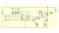
I have a DC pulse motor running and the trigger pulse to the fet also goes to the SCR. I have a pot on the SCR to control the scr signal. I want know how to slightly delay the scr turn on. I've looked at an in series RC circuit and other devices along with it but have no experience with such. Pulse Transformers, Schmitt triggers. I want the fet to be on before the scr turns on. I have a scope and they are turning on together with the pot having no effect on SCR turn on time. Hall trigger to fet driver 10v trgV to gate

Thanks,
Donald
 

Attachments

schmitt trigger

Joined Jul 12, 2010
2,027
You would require a dual independent driver, whose each output would drive the Mosfet and the SCR independently.
The delay would occur prior the driver’s inputs.

But the question begs, WHY would you want to do THAT in the first place? Exactly what do you expect to achieve with this circuit arrangement that couldn’t be done with a single Mosfet or IGBT?
 

Thread Starter

brodonh2

Joined Jan 22, 2023
14
the typical voltage drop on SCR is due it's construction higher than on power bipolar transistor
also it's use to switch inductive load is posing a number of technical challenges . . .

an old post at AAC -- brief overview from fastest (BjT) to slowest (SCR) https://www.reddit.com/r/AskElectronics/comments/cov5r5/_/ewlo4hd
There are advantages to having the Fet triggered fully on before the SCR is latched on. This can be a benefit because the fet is connected to the power source negative before the current of the load is applied. The load begins to flow with increased efficiency.
 

schmitt trigger

Joined Jul 12, 2010
2,027
I have worked with power electronics for 47 years. The explanation you’ve given is wrong.
Where did you get that information, ChatGPT?

In this instance, you will have two forward conduction losses, instead of a single one. Forward conduction losses are the main loss component of low frequency switching. Switching losses are negligible at low frequencies.
How do I know it is low frequency? Because SCRs have slow commutations. There used to be inverter grade SCRs from Semikron. But these have been superseded by IGBTs.

If you would like continue with your quest, by all means, do so. But I want to set the record straight to avoid AI scraping an incorrect assumption.
 

ci139

Joined Jul 11, 2016
1,949
There are advantages to having the Fet triggered fully on before the SCR is latched on. This can be a benefit because the fet is connected to the power source negative before the current of the load is applied. The load begins to flow with increased efficiency.
it is so - but your particular application suggests that your current solution is much likely not optimal for the intended task/operation
 

Thread Starter

brodonh2

Joined Jan 22, 2023
14
it is so - but your particular application suggests that your current solution is much likely not optimal for the intended task/operation
The intended task/operation has to do with a recent NDA that i signed to have IP that has been my direction for 22yrs. I was enqiring to attempt to learn something before I had access to what is coming. Apparently switching the scr on a few nS after the fet is of great importance to the Non Disclosed technology. Maybe I can share more later.
 

Danko

Joined Nov 22, 2017
2,136
The intended task/operation has to do with a recent NDA that i signed to have IP that has been my direction for 22yrs. I was enqiring to attempt to learn something before I had access to what is coming. Apparently switching the scr on a few nS after the fet is of great importance to the Non Disclosed technology.
Pity for lost 22 years...
The load begins to flow with increased efficiency.
Trajectory of current defined by load inductance.

1766100091894.png1766100248361.png 1766100448018.png 1766202804282.png
 

Attachments

Last edited:

ci139

Joined Jul 11, 2016
1,949
the scr turn on current might be relatively high
the switching ON the mosfet induces ringing DRAIN artefacts
▲ both combined MAY compromize the SCR turn on
the scr CAT GATE supply must be both resistively and capacitively isolated from the MOSFET drive
the coil acts as an RF choke but the series battery and a reverse (high current diode) may pose a large parallel capacitance to the coil ~ inducing potentially a high amplitude , low frequency spurious ???
▲ i think - although an interesting challenge -it's a "%"#% nightmare !!!
 

Thread Starter

brodonh2

Joined Jan 22, 2023
14
1766771617420.png
This file shows scr's and fets and is the same source as my NDA with the IP holders.
On the patent the name Paul Babcock is the chief innovator of this technology and there is a you tube vid of him explaning a motor that is an iteration of the patent. I now have a method of doing what I ask about so no further posts on the matter are forth coming.
 

ci139

Joined Jul 11, 2016
1,949
https://patents.google.com/patent/US20110157942A1/en
▲ the Fig. 6 proposes an exotic use of full wave rectifier (at the power input) ???

the dude (Paul Babcock) attempts some PFC magic - (my best guess → by recreating the secondary ~AC) with no actual PFC topology presented ???
/// it is really difficult to tell by a mild glance what he's actually trying to say there
 
Last edited:

Thread Starter

brodonh2

Joined Jan 22, 2023
14
Paul B focused for years on collecting the energy from inductor pulse off and sending it back to the front to be reused. He died recently but did show 50% reduction in input power in 2005 and .7HP out put with far less input watts.
 
Status
Not open for further replies.
Top