What caused AC harmonics and why differential amplifier can't eliminate them?

Status
Not open for further replies.

MisterBill2

Joined Jan 23, 2018
27,888
REturning to the original complaint in post #1,which appears to be power frequency harmonics in the output signal, and tha complaint being that they can not be magicaly extracted somehow. At this point my conclusion about the problem is a bit different, and likewise my suggestion for a solution.The fiirst suggestion that I offer is to power that entire expensive amplifier package from a battery supply that is not connected to the mains in any way during the amplifier use. My second suggestion is to use a connection to the patient scheme similar to the scheme usedfor connecting heart monitors for use during surgery. THAT SCHEME uses two attachments to a differential input AND a third nearby attachment for the common reference voltage for that input pair. AND to use for tthose input connections fairly short unshielded wires with the majority of the connection being in a single, shielded cable with the reference common to the shield at one point only. THAT approach will reduce the pickup from the rather high noise voltage field in the patient vicinity.
 
Last edited:

MisterBill2

Joined Jan 23, 2018
27,888
For ths two scope traces in post #80, we have no hint as to the amplitude not the sweep speed. My guess there is that the noise peaks are from amplifier overload and saturation.
 

Thread Starter

Secan

Joined Sep 20, 2024
205
REturning to the original complaint in post #1,which appears to be power frequency harmonics in the output signal, and tha complaint being that they can not be magicaly extracted somehow. At this point my conclusion about the problem is a bit different, and likewise my suggestion for a solution.The fiirst suggestion that I offer is to power that entire expensive amplifier package from a battery supply that is not connected to the mains in any way during the amplifier use. My second suggestion is to use a connection to the patient scheme similar to the scheme usedfor connecting heart monitors for use during surgery. THAT SCHEME uses two attachments to a differential input AND a third nearby attachment for the common reference voltage for that input pair. AND to use for tthose input connections fairly short unshielded wires with the majority of the connection being in a single, shielded cable with the reference common to the shield at one point only. THAT approach will reduce the pickup from the rather high noise voltage field in the patient vicinity.
Without opening the unit..can you pls illustrate or draw how this reference pickup look like? I cant imagine what you are saying..i have difficulty building a person size faraday cage. So if anything can help minimize all noise. Ill listen. Tnx
 

drjohsmith

Joined Dec 13, 2021
1,629
you have a few problems with any ecg machine design

a. the leads are long, badly screened , and the load is high impedance .

b. the signals you are measuring are very small

c. mains induced radiated interference is everywhere, and not a constant frequency

d. the signal your looking for is around the same frequency as the mains interference.

the differential amplifiers are aimed at minimising the common mode pickup, the interference thats on both the wires,

where I have my twice a year ecg, if I'm on the 12 lead set they often have to turn off the fluorescent lights due to the emi from their chokes .

the fact that when you run on battery, the interference disappears, indicates the differential amps are working perfectly attenuation the common mode pickup.

which points back at the ac dc power pack.
when you plug that in you see the interference.

have you tried a different ac dc power pack?

all circuits have a given power supply rejection ratio,
I.e. a indication of the amount of noise on the circuits power supply that you will se on the output .

when you use the ac dc power pack, does the interference change as you move it around ?
im wondering if the pack is radiating , is it anywhere near the ecg leads ?

if if is radiating, you need to get a new pack.

the other route is that the pack is just putting out a terrible dc, with so many harmonics on it, the the psrr of the circuit can't cope.
in which case you need a new pack.
 

drjohsmith

Joined Dec 13, 2021
1,629
btw:
if your thinking of selling this, or even giving it away , and claim its medical qualified, or for medical usage, u need to have it approved by a regulatory authority.

things like air gaps and power supplies become critical.
 

Thread Starter

Secan

Joined Sep 20, 2024
205
you have a few problems with any ecg machine design

a. the leads are long, badly screened , and the load is high impedance .

b. the signals you are measuring are very small

c. mains induced radiated interference is everywhere, and not a constant frequency

d. the signal your looking for is around the same frequency as the mains interference.

the differential amplifiers are aimed at minimising the common mode pickup, the interference thats on both the wires,

where I have my twice a year ecg, if I'm on the 12 lead set they often have to turn off the fluorescent lights due to the emi from their chokes .

the fact that when you run on battery, the interference disappears, indicates the differential amps are working perfectly attenuation the common mode pickup.

which points back at the ac dc power pack.
when you plug that in you see the interference.

have you tried a different ac dc power pack?

all circuits have a given power supply rejection ratio,
I.e. a indication of the amount of noise on the circuits power supply that you will se on the output .

when you use the ac dc power pack, does the interference change as you move it around ?
im wondering if the pack is radiating , is it anywhere near the ecg leads ?

if if is radiating, you need to get a new pack.

the other route is that the pack is just putting out a terrible dc, with so many harmonics on it, the the psrr of the circuit can't cope.
in which case you need a new pack.
I'm using advanced active electrodes with 10ohm lead impedance so it won't attract much interference current. Anyway, what do you mean "mains induced radiated interference is everywhere, and not a constant frequency"? What frequencies are they? you mean only the 60Hz and harmonics like 120Hz, 180Hz, 240Hz?

Btw.. my specific application is probing 1000Hz microvolt signal in the nerve plexus biopotentials so I can eliminate frequencies below 100Hz. My applicaiton is not EEG nor EMG. How do you make a high pass circuit that can eliminate all frequency below 100Hz?
 

drjohsmith

Joined Dec 13, 2021
1,629
I'm using advanced active electrodes with 10ohm lead impedance so it won't attract much interference current. Anyway, what do you mean "mains induced radiated interference is everywhere, and not a constant frequency"? What frequencies are they? you mean only the 60Hz and harmonics like 120Hz, 180Hz, 240Hz?

Btw.. my specific application is probing 1000Hz microvolt signal in the nerve plexus biopotentials so I can eliminate frequencies below 100Hz. My applicaiton is not EEG nor EMG. How do you make a high pass circuit that can eliminate all frequency below 100Hz?
re my comment about mains not being constant .
a filter has a bandwidth , mains frequency is unfoftunatly instantaneously 60 hz plus or minus a few hz, even if on average the frequency is 60 hz,
so if you want to filter the mains out, you need a few hz filter bandwidth.

can you share links to those probes your using please , they sound interesting.

to directly answer your question on best way to eliminate frequencies below 100 hz , the best is to digitised then fft filter and re construct . its what I've done on a few similar equipment.

you can even in digits, be clever and recognise the actual phase of the 50 / 60 hz signal, and totaly nullify it.

even a cheap Pi computer for usd 10 can do this well.

but, there is an old saying, best not to get false signals in rather than try to filter after, as filtering is always going to loosereal signal.

as your interference disappeared when you used battery, then that identifies you cause of the problems,

check with a scope the noise on the dc of the powersupply when your seeing the interference.

also, if your only filtering you signal at 100hz, that spectrum u initially showed is still going to have lots of spikes on it
you need at decent power supply to your unit


share a screen grab please .
 

MisterBill2

Joined Jan 23, 2018
27,888
Without opening the unit..can you pls illustrate or draw how this reference pickup look like? I cant imagine what you are saying..i have difficulty building a person size faraday cage. So if anything can help minimize all noise. Ill listen. Tnx
If you do not understand what a reference pickup looks like , understand that it looks like the other pickups you are using. What makes it a reference pickup is that it is used as a common reference for the signals.

I suggest that you study and understand accurately the use and application of ECG probes and instrumentation. I see a serious knowledge gap.
 

Thread Starter

Secan

Joined Sep 20, 2024
205
If you do not understand what a reference pickup looks like , understand that it looks like the other pickups you are using. What makes it a reference pickup is that it is used as a common reference for the signals.

I suggest that you study and understand accurately the use and application of ECG probes and instrumentation. I see a serious knowledge gap.
Ah. In EEG and ECG, amplifier reference pickup is called ground (or virtual ground). If you don't connect it, there is no signal because the inputs are floating. The word "reference" in EEG and ECG is reserved for the In- input, the In+ is called active.

Anyway. I noticed if you put the ground (amplifier reference pickup) in EEG in the wrist instead of in the head, the powerbank noise magnitude is larger. I didn't use the AC adaptor much because I avoid using it to avoid surges. Why is it if the (reference pickup) or ground is further away, the noise is larger? Is it because the resistance is more in the skin? But then, a amplifier reference invariant to the skin resistance because it just sets the common mode range of the differential input amplifer. As someone wrote in the net:

"The "ground" electrode simply tries to keep the measured bag of conductive saltwater at midpoint common mode range of the differential input amplifier.
There is ideally no current through the "ground" electrode terminals so it will bias the measured biomass blob even if it had megaohms of impedance."
 

Thread Starter

Secan

Joined Sep 20, 2024
205
re my comment about mains not being constant .
a filter has a bandwidth , mains frequency is unfoftunatly instantaneously 60 hz plus or minus a few hz, even if on average the frequency is 60 hz,
so if you want to filter the mains out, you need a few hz filter bandwidth.

can you share links to those probes your using please , they sound interesting.

to directly answer your question on best way to eliminate frequencies below 100 hz , the best is to digitised then fft filter and re construct . its what I've done on a few similar equipment.

you can even in digits, be clever and recognise the actual phase of the 50 / 60 hz signal, and totaly nullify it.

even a cheap Pi computer for usd 10 can do this well.

but, there is an old saying, best not to get false signals in rather than try to filter after, as filtering is always going to loosereal signal.

as your interference disappeared when you used battery, then that identifies you cause of the problems,

check with a scope the noise on the dc of the powersupply when your seeing the interference.

also, if your only filtering you signal at 100hz, that spectrum u initially showed is still going to have lots of spikes on it
you need at decent power supply to your unit


share a screen grab please .
Active electrodes have gain 1 unity buffer amplifier inside the electrode with huge input impedance and only 10ohm output impedance. The purpose is so it won't attract interference current in the wires creating huge voltage at the amplifier input (from V=IR)

Please look at this chinese website with teardown of the gammabox (which I also have).

脑电信号采集时参考电极和接地电极的作用及区别 - 知乎

after translation of the web contents. It didn't explain how it works. But I found someone mentioning a theory how it works:


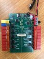
gamma box inside.jpg


Active Electrode Circuit Design — OpenBCI Forum


gammabox impression.JPG

Here is the spec sheet of the REF200 chipset used:

REF200 Dual Current Source and Current Sink datasheet (Rev. C)

Guys. based on the pcb schematic and REF200 chip used. Is William theory of its operation correct above (it has only 2 wire, ordinarily there should be 3 wires as 2 is for power supply and third wire for data)?
 

drjohsmith

Joined Dec 13, 2021
1,629
dont know where your going with this.
you have shown in an earlier post that the noise spikes you see are mains based, and disappear when you power by battery.

qed. the source of your problems is the power supply.

you are also saying you have powered pads,

these are another source for noise to get in if you have a noisy power supply.

qed . the source of your noise is the power supply.
 

Thread Starter

Secan

Joined Sep 20, 2024
205
re my comment about mains not being constant .
a filter has a bandwidth , mains frequency is unfoftunatly instantaneously 60 hz plus or minus a few hz, even if on average the frequency is 60 hz,
so if you want to filter the mains out, you need a few hz filter bandwidth.

can you share links to those probes your using please , they sound interesting.
You wrote above to share about the active probes im using so shared them in my last message..and asking how the signal is sent in 2 wire power supply which it has inside the lead to the active electrode.

My harmonics prob in ac adaptor is solved. It is just ungrounded.
 

drjohsmith

Joined Dec 13, 2021
1,629
You wrote above to share about the active probes im using so shared them in my last message..and asking how the signal is sent in 2 wire power supply which it has inside the lead to the active electrode.

My harmonics prob in ac adaptor is solved. It is just ungrounded.
thanks, thought it was done , just wanted to check.

fyi. the mains powered medical gear i use does not have mains spikes , and its not earthed.

if you you have an earth loop, such as using a none isolated usb, that would nullify you equipments medical qualification., and cause the problem your seeing.

I've not seen active but dumb probes.
dumb as in just an amplifier .

power a d signal over two wires is easy, its called phantom powering, mostly used in microphone circuits.
 

Thread Starter

Secan

Joined Sep 20, 2024
205
thanks, thought it was done , just wanted to check.

fyi. the mains powered medical gear i use does not have mains spikes , and its not earthed.

if you you have an earth loop, such as using a none isolated usb, that would nullify you equipments medical qualification., and cause the problem your seeing.

I've not seen active but dumb probes.
dumb as in just an amplifier .

power a d signal over two wires is easy, its called phantom powering, mostly used in microphone circuits.
Oh, didn't know you were a doctor. Say, do your gears also have large DC offset below 0.5Hz? When I set the bandwidth between 0 to 1000Hz. I got huge almost -250mV dc offset. What value do you get for 0Hz to your cutoff? When I made the passband 0.1Hz to 1000Hz, there is only 1mV baseline wander. When I set it to 5hz to 1000Hz. no more DC offset (is this also called baseline shift?)

I wonder if purely instrumentation amplifier unit is similar in the DC offset to a unit that uses ADCs to subtract common-mode digitally.

My next step now is get the purest 5V DC as there is 60uV common-mode noise from the powerbank 3.7V to 5V buck/booster converter. I don't know if the unit can subtract 60uV fully by firmware/software..
 

drjohsmith

Joined Dec 13, 2021
1,629
Oh, didn't know you were a doctor. Say, do your gears also have large DC offset below 0.5Hz? When I set the bandwidth between 0 to 1000Hz. I got huge almost -250mV dc offset. What value do you get for 0Hz to your cutoff? When I made the passband 0.1Hz to 1000Hz, there is only 1mV baseline wander. When I set it to 5hz to 1000Hz. no more DC offset (is this also called baseline shift?)

I wonder if purely instrumentation amplifier unit is similar in the DC offset to a unit that uses ADCs to subtract common-mode digitally.

My next step now is get the purest 5V DC as there is 60uV common-mode noise from the powerbank 3.7V to 5V buck/booster converter. I don't know if the unit can subtract 60uV fully by firmware/software..
im now a retired consultant to big electronics design house.

amongst otheres, spent a few years designing a one chip " ecg" "eeg" machine ,
that also does things like clamp interface .

problem with common mode, or even power supply noise, is it gets every where , and is incredible hard to filter / cancel out .

yes the stuff I worked on does not have the problems you have,
but it also has multi country medical approval, which costs many 10 of thousands of dollars for each country . so no relation to the low cost , none approved stuff you seem to have .

hope you are not putting that gear on humans,

one tip, as mentioned already, could be you have ground noise , from earth loops. a clue is you say the noise disappears when on battery .
I mentioned above about usb, you need to use a medical approved usb connection. these are only a few hundred dollars , and isolate the USB signals.
a quick test you can do , is use the USB from a laptop, but ensure there is no other connections on the laptop, I e battery powered laptop, no external monitors , and next no external anything, key board, mouse, camera et all. just a standard, battery powered laptop. see if the noise disappears.

re filtering, and dc.
dc offset is measured with respect to "ground" . none of the measuring gear should be grounded , so no dc offset..

it again points to your setup not being medical grade.

any base line wander is best taken out by a compensation offset signal into the differential bias of the instrumentation amplifier.
this needs to be dynamic, effectively following the changing offset.
a simple method is to digital filter out above say 0.5 hz, to arrive at a dc voltage to applied back to the input.
its not that simple, but it gives you an idea.

the problem is the subject your trying g to measure, is a great big capacitive antenna , that picks up just about any emissions around

an example, use your car keys to lock your car , keep walking away from car till it no longer locks. walk back further say 6 m , then put fob to your head ... the car will now lock !
your body is a great antenna.
 

Thread Starter

Secan

Joined Sep 20, 2024
205
im now a retired consultant to big electronics design house.

amongst otheres, spent a few years designing a one chip " ecg" "eeg" machine ,
that also does things like clamp interface .

problem with common mode, or even power supply noise, is it gets every where , and is incredible hard to filter / cancel out .
Is it not you only need to filter 60Hz and 120Hz and 180Hz or the harmonics? Also even if it can't be filtered out. The signal can still ride on them if they won't get clipped. The unit has large +250mV to -250mV range so any signal can be captured without clipping (also they are just ADCs, see detail below)..

The unit is used by almost all BCI (Brain Computer Interface) research centers. It is not used for medical.

yes the stuff I worked on does not have the problems you have,
but it also has multi country medical approval, which costs many 10 of thousands of dollars for each country . so no relation to the low cost , none approved stuff you seem to have .

hope you are not putting that gear on humans,

one tip, as mentioned already, could be you have ground noise , from earth loops. a clue is you say the noise disappears when on battery .
I mentioned above about usb, you need to use a medical approved usb connection. these are only a few hundred dollars , and isolate the USB signals.
a quick test you can do , is use the USB from a laptop, but ensure there is no other connections on the laptop, I e battery powered laptop, no external monitors , and next no external anything, key board, mouse, camera et all. just a standard, battery powered laptop. see if the noise disappears.
The harmonics disappeared when I grounded the AC adaptor. We didn't use ground in my country but I managed to connect the ground to the water tank outside.

Did you mean I must use the USB in the laptop to power the unit? But the unit power requirement is 1.3A. The laptop may not have that power. Also is it not the lithium ion in laptop is also 3.7V so need boost/buck converter to reach 5V too?

re filtering, and dc.
dc offset is measured with respect to "ground" . none of the measuring gear should be grounded , so no dc offset..

it again points to your setup not being medical grade.

any base line wander is best taken out by a compensation offset signal into the differential bias of the instrumentation amplifier.
this needs to be dynamic, effectively following the changing offset.
a simple method is to digital filter out above say 0.5 hz, to arrive at a dc voltage to applied back to the input.
its not that simple, but it gives you an idea.
The unit doesn't use any instrumentation amplifier. See message #89 where I shared some info. Basically, what the unit does is this. If you subtract the signal of channel A from the signal of channel B, you will automatically cancel any signal C that is common to both: A = A_0 + C, B = B_0 + C, B - A = B_0 + C - A_0 - C = B_0 - A_0. This can be done by any software that is able to perform a subtraction of channel data".

the problem is the subject your trying g to measure, is a great big capacitive antenna , that picks up just about any emissions around

an example, use your car keys to lock your car , keep walking away from car till it no longer locks. walk back further say 6 m , then put fob to your head ... the car will now lock !
your body is a great antenna.
But the capacitive coupling is only 60Hz is it not? I don't need below 100Hz. I need 500Hz to 1000Hz so the 60Hz capacitive coupling would not be a problem right? Why is it still at problem at 500Hz to 1000Hz??

Thank you.
 

drjohsmith

Joined Dec 13, 2021
1,629
Is it not you only need to filter 60Hz and 120Hz and 180Hz or the harmonics? Also even if it can't be filtered out. The signal can still ride on them if they won't get clipped. The unit has large +250mV to -250mV range so any signal can be captured without clipping (also they are just ADCs, see detail below)..

The unit is used by almost all BCI (Brain Computer Interface) research centers. It is not used for medical.


The harmonics disappeared when I grounded the AC adaptor. We didn't use ground in my country but I managed to connect the ground to the water tank outside.

Did you mean I must use the USB in the laptop to power the unit? But the unit power requirement is 1.3A. The laptop may not have that power. Also is it not the lithium ion in laptop is also 3.7V so need boost/buck converter to reach 5V too?


The unit doesn't use any instrumentation amplifier. See message #89 where I shared some info. Basically, what the unit does is this. If you subtract the signal of channel A from the signal of channel B, you will automatically cancel any signal C that is common to both: A = A_0 + C, B = B_0 + C, B - A = B_0 + C - A_0 - C = B_0 - A_0. This can be done by any software that is able to perform a subtraction of channel data".


But the capacitive coupling is only 60Hz is it not? I don't need below 100Hz. I need 500Hz to 1000Hz so the 60Hz capacitive coupling would not be a problem right? Why is it still at problem at 500Hz to 1000Hz??

Thank you.
re usb powering.
no I dont mean that.
your board seems to have a usb connector.
is this connected when the board is powered by the external psu ?
if yes , the USB can be a source of the noise,
usb has ground, and power lines, these are referenced to the pc the USB is plugged into, if that PC is mains powered, then there is a great potential to pick up noise, and your equipment should not be connected to humans.

filtering out a frequency , dead easy in software, fft -> filter -> ifft.
allows filters impossible to make in circuits.

problem, where has interference come from, is it modulating with your signals , causing distortion, and the damed frequency is not stable.

do not ever earth a medical grade power supply, it needs to be floating ...

sorry, im seriously worried that if I help further, I might be being involved in something that contravenes ethical standards and or safety
 

Thread Starter

Secan

Joined Sep 20, 2024
205
re usb powering.
no I dont mean that.
your board seems to have a usb connector.
is this connected when the board is powered by the external psu ?
if yes , the USB can be a source of the noise,
usb has ground, and power lines, these are referenced to the pc the USB is plugged into, if that PC is mains powered, then there is a great potential to pick up noise, and your equipment should not be connected to humans.

filtering out a frequency , dead easy in software, fft -> filter -> ifft.
allows filters impossible to make in circuits.

problem, where has interference come from, is it modulating with your signals , causing distortion, and the damed frequency is not stable.

do not ever earth a medical grade power supply, it needs to be floating ...

sorry, im seriously worried that if I help further, I might be being involved in something that contravenes ethical standards and or safety
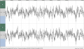
I always used battery power when running the laptop and the unit. The reason I know the noises come from the powerbank is because the Anker PowerCore Essential 20000 PD has twice the noise of the Xiaomi PLM8ZM which is said to have the lowest noise. The following is from the Anker. It is not directly measuring the 5V of the powerbank using oscilloscope of course, but output from the g.USBamp $4000 software:

anker noise 2 channels.PNG

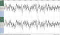
The following noise is from the Xiaomi, note the display scale is half lesser so less noise:

xiaomi noise b 2 channels.PNG


They are not bipolar but each channel is unipolar. My concern is whether they can subtract when in actual use with probes. If I just subtract the above using channel 1 - channel 2. I got only 3uV background noise. I don't noise if it works in actual too.

So with my laptop always 100% battery powered, I pulled out all the AC and unplug all wires surrounding it when using it. How do I check the noise coming from the laptop usb port which is connected to the unit? It's a Microsoft Surface 2017 notebook.

Also I want to know the effect of the powerbank ripples to the whole unit.. like is there a noise direct from it that can affect the whole unit I'm not aware of? like modulating the signals?

About grounding, my house if run by 100% GFCI breakers and i don't use grounding since millions of homes in the Philippes never use grounding, so no problem about not grounding the units. I know they should use virtual ground in the electrode ground probes which it did. Anyway I will always use 5V battery when running it and not AC.

I'm pondering this statement of yours: "problem, where has interference come from, is it modulating with your signals , causing distortion, and the damed frequency is not stable.".. can this affect 500Hz to 1000Hz?? like modulating it? Last resort is to get human size Faraday cage.
 
Status
Not open for further replies.
Top