Voltage Divider with Three Outputs

Thread Starter

Purple_Letters

Joined Apr 24, 2017
20
No, it is not correct. Those are not the voltages you need. You also need to use resistor values that are much smaller than the resistances in the original circuit.

Forget about the voltage divider for a moment. Analyze the original circuit and figure out the voltages at each node and the currents in each branch. THAT is your starting point.
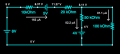
Moving clockwise around the circuit from the left hand side, the current in the resistors is I1 = 0.000163A and the voltage drop is V1 = 1.63V, I2 = 0.000163A and V2 = 3.26V, I3 = 0.0000822A and V3 = 4.11V, I4 = 0.0000811A and V4 = 8.11V. I used Kirchhoff's laws to calculate these values.

The potential across battery 1 is 0V to 8V, battery 2 is 6.37V to 11.37V and battery 3 is 4V to 0V.

What would my next step be?
 
Last edited:

WBahn

Joined Mar 31, 2012
33,126
Sorry, I can't seen to edit my above post. It was supposed to read:

Moving clockwise around the circuit from the left hand side, the current in the resistors is I1 = 0.000163A and the voltage drop is V1 = 1.63V, I2 = 0.000163A and V2 = 3.26V, I3 = 0.0000822A and V3 = 4.11V, I4 = 0.0000811A and V4 = 8.11V. I used Kirchhoff's laws to calculate these values.
This is too ambiguous to do much good. I don't know what direction these currents are flowing or which resistors each voltage drop is for or what the polarity of that drop is. Annotating your diagram is a MUCH better way to communicate this information.

The potential across battery 1 goes from 0V to 8V, battery 2 goes from 6.37V to 11.37V and battery 3 goes from 4V to 0V.
This is much more useful as it allows me to fairly confidently do what you should really have done. But note that even here you say things like battery 1 and battery 2 but you never show on your diagrams which battery is which. At least here I can figure it out fairly easily -- but don't make people that are trying to help you for free have to jump through a bunch of hoops figuring out information that you should have indicated explicitly on your diagram.

Edit_2017-04-24_1.png


See how that diagram captures everything so nicely -- and it was trivial to do the annotations just using Paint.

What would my next step be?
Next you want to find the lowest voltage node on the entire diagram and make it the 0 V reference node (if it isn't already) so that none of the node voltages are negative.

Then list the voltages of the nodes on each side of each of the batteries. These are the voltages that your voltage divider needs to produce.

Next look at the largest current anywhere in your circuit. You are going to want the total current in the voltage divider power supply to be at least an order of magnitude greater than this, if possible.
 

Thread Starter

Purple_Letters

Joined Apr 24, 2017
20
This is too ambiguous to do much good. I don't know what direction these currents are flowing or which resistors each voltage drop is for or what the polarity of that drop is. Annotating your diagram is a MUCH better way to communicate this information.


This is much more useful as it allows me to fairly confidently do what you should really have done. But note that even here you say things like battery 1 and battery 2 but you never show on your diagrams which battery is which. At least here I can figure it out fairly easily -- but don't make people that are trying to help you for free have to jump through a bunch of hoops figuring out information that you should have indicated explicitly on your diagram.

View attachment 125409


See how that diagram captures everything so nicely -- and it was trivial to do the annotations just using Paint.


Next you want to find the lowest voltage node on the entire diagram and make it the 0 V reference node (if it isn't already) so that none of the node voltages are negative.

Then list the voltages of the nodes on each side of each of the batteries. These are the voltages that your voltage divider needs to produce.

Next look at the largest current anywhere in your circuit. You are going to want the total current in the voltage divider power supply to be at least an order of magnitude greater than this, if possible.

Thank you so much for creating that diagram, sorry that I was not very clear. I really appreciate your help!

When you refer to a voltage node, I'm not entirely sure what you mean? Does this refer to the 4V point above the 4V battery? As this is the only battery where the voltage is a negative across the battery? Or is this the points where there is a voltage of 0V? There are no points below 0V. Doesn't the diagram already include the voltage nodes on either side of the battery? I'm confused because the change in voltage across each supply is 8V, 5V, 4V, but do I have to create a voltage divider with 8V, 6.37V, 11.37V, 4V and 0V outputs?

The largest current is 0.000163A, so I would want the total current in the voltage divider power supply to be 0.000163A*10=0.00163A?
 
Last edited:

WBahn

Joined Mar 31, 2012
33,126
Voltage is always a voltage difference. When we talk about the voltage ON or AT a particular point (or node) we are implicitly talking about the voltage difference between that point and some arbitrarily chosen 0 V reference point. So when you connect a 10 V battery between node A (to the negative terminal) and node B, you are not establishing the voltage at either node A or B, but merely establishing that the voltage at node B is 10 V higher than the voltage at node A.

We could have chosen ANY node in that diagram to be the 0 V reference node (often called "ground"). If we had chosen the top-right node as the 0 V reference, then all of the voltages shown in my diagram would have been 8.11 V lower, so some would have been positive and some would have been negative. Often there is a node that jumps at as being the obvious choice for the 0 V reference and that was true here with the bottom node being the obvious choice. But what if the 4 V battery had been flipped around?

We don't HAVE to have all positive node voltages (i.e., pick the lowest voltage node to be 0 V), it just makes like easier.
 

WBahn

Joined Mar 31, 2012
33,126
Oh, and yes, you want to make a voltage divider with 0V (which you get for free), 4.00 V, 6.37 V, 8.00 V, 11.37 V (as close as you can make them with what you have available).
 

Thread Starter

Purple_Letters

Joined Apr 24, 2017
20
Voltage is always a voltage difference. When we talk about the voltage ON or AT a particular point (or node) we are implicitly talking about the voltage difference between that point and some arbitrarily chosen 0 V reference point. So when you connect a 10 V battery between node A (to the negative terminal) and node B, you are not establishing the voltage at either node A or B, but merely establishing that the voltage at node B is 10 V higher than the voltage at node A.

We could have chosen ANY node in that diagram to be the 0 V reference node (often called "ground"). If we had chosen the top-right node as the 0 V reference, then all of the voltages shown in my diagram would have been 8.11 V lower, so some would have been positive and some would have been negative. Often there is a node that jumps at as being the obvious choice for the 0 V reference and that was true here with the bottom node being the obvious choice. But what if the 4 V battery had been flipped around?

We don't HAVE to have all positive node voltages (i.e., pick the lowest voltage node to be 0 V), it just makes like easier.
Ok, that makes sense. So, for this example, I will keep all of the voltages at the nodes the same as in the picture you sent? (If the other battery were the opposite way around, then I guess I would pick 4V to be the 0V reference node? So everything would be 4V lower?)

To determine the voltages that my voltage divider need to provide, am I correct in thinking I need an 8V input, 11.37V input and a 4V input?
 

WBahn

Joined Mar 31, 2012
33,126
You also need a 6.37 V input. Remember, the purpose of your voltage divider circuit is to supply the voltages at the terminals of each of the batteries so that you can remove the batteries. So you will need to connect one wire from your voltage divider to pin the node at the negative terminal of the 5 V battery to 6.37 V and another wire from your voltage divider to pin the node at the positive terminal of the 5 V battery to 11.37 V.
 

Thread Starter

Purple_Letters

Joined Apr 24, 2017
20
Oh, and yes, you want to make a voltage divider with 0V (which you get for free), 4.00 V, 6.37 V, 8.00 V, 11.37 V (as close as you can make them with what you have available).

Ok, so I need four outputs plus the ground, and five resistors then? The ratio of these is 1 : 1.5925 : 2 : 2.8425, correct? So if my initial resistor was 100 ohms, R2 would be 160 ohms, 200 ohms, 290 ohms, correct? How do I work out the fifth resistor? Also, I do not have these resistors available, I only have:
- 1kΩ, 2kΩ, 5kΩ, 10kΩ, 100kΩ, 1MΩ resistors
− 100, 200, 500 and 700Ω 5W resistors
 

WBahn

Joined Mar 31, 2012
33,126
Why five resistors? Remember, you get to set the output of the voltage supply to be anything less than or equal to 30 V.

How are you coming up with those ratios? For instance, I can see where you are getting the 1.5925 from, but is this REALLY the ratio of the bottom two resistors in your divider? If the bottom resistor were R and it produced the 4 V output, then what would the voltage be at the top of the second resistor if it was also R (for a ratio of 1:1)? Would increasing that ratio to 1.5925 increase or decrease the voltage at the top of the second resistor?
 

WBahn

Joined Mar 31, 2012
33,126
With only four resistor values available (for your power resistors) it is very unlikely that you will be able to come close to the ideal output voltages from your divider unless the target circuit was very carefully constructed by the instructor. Given the round numbers used for everything, I doubt that this was the case. So that leads me to suspect that you are going to have a bunch of each size available to you. It would be nice if the problem had given a tolerance for how well your modified circuit was supposed to match the original circuit. So you will need to use series/parallel combinations to get close to the desired voltages (but without the tolerances you don't know how close is close enough).

Also, with just needing a couple of milliamps from the voltage divider source, you may be able to use the higher valued resistors. It is probably safe to assume that they are at least 1/8 watt.

You might ask the instructor what the power ratings on those resistors are, how well you need to match the original circuit, and how many of each resistor value you have available.
 

Thread Starter

Purple_Letters

Joined Apr 24, 2017
20
With only four resistor values available (for your power resistors) it is very unlikely that you will be able to come close to the ideal output voltages from your divider unless the target circuit was very carefully constructed by the instructor. Given the round numbers used for everything, I doubt that this was the case. So that leads me to suspect that you are going to have a bunch of each size available to you. It would be nice if the problem had given a tolerance for how well your modified circuit was supposed to match the original circuit. So you will need to use series/parallel combinations to get close to the desired voltages (but without the tolerances you don't know how close is close enough).

Also, with just needing a couple of milliamps from the voltage divider source, you may be able to use the higher valued resistors. It is probably safe to assume that they are at least 1/8 watt.

You might ask the instructor what the power ratings on those resistors are, how well you need to match the original circuit, and how many of each resistor value you have available.
If the ratio were 1:1, and the bottom resistor produces 4V, then the voltage at the top of the second resistor would be 8V? I'm not entirely sure. Increasing it to 1.5925 would increase the voltage above 8V? If this is the case, then the resistor which produces a voltage of 4V must be a greater resistance than the resistor that produces a voltage of 6.37V.

Assuming R1 is the resistor between 11.37 and 8V, R2 is the resistor between 8V and 6.37V, R3 is the resistor between 6.37V and 4V and R4 is the resistor between 4V and 0V. Then the resistance of R4 can be picked as any resistor. The resistance of R3 must be 0.52952 the resistance of R4 (2.37 : 4 = 0.52952 : 1), the resistance of R2 must be 0.4075 the resistance of R4, and the resistance of R1 must be 0.8425 the resistance of R4. Is this correct?

I am unable to contact the professor prior to my laboratory session unfortunately, so I really have no idea whether I can use multiple of the resistors... But I think it is better to create a circuit using multiple, as this will allow me to create the most accurate circuit?
 
Last edited:

Thread Starter

Purple_Letters

Joined Apr 24, 2017
20
With only four resistor values available (for your power resistors) it is very unlikely that you will be able to come close to the ideal output voltages from your divider unless the target circuit was very carefully constructed by the instructor. Given the round numbers used for everything, I doubt that this was the case. So that leads me to suspect that you are going to have a bunch of each size available to you. It would be nice if the problem had given a tolerance for how well your modified circuit was supposed to match the original circuit. So you will need to use series/parallel combinations to get close to the desired voltages (but without the tolerances you don't know how close is close enough).

Also, with just needing a couple of milliamps from the voltage divider source, you may be able to use the higher valued resistors. It is probably safe to assume that they are at least 1/8 watt.

You might ask the instructor what the power ratings on those resistors are, how well you need to match the original circuit, and how many of each resistor value you have available.
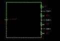
Would a voltage divider like this work? I can make R1=1000 ohms from two 500 ohms resistors in series, R2=500 ohms is given, R3=400 ohms can be made from two 200 ohm resistors in series and R4=900 ohms can be made from a 700 ohm resistor and a 200 ohm resistor. The output values are not exactly correct, but I think they are a reasonable approximation, using the materials I am given?Screenshot (2366)_LI.jpg

If this is correct.. How do I go about connecting it to my target circuit?

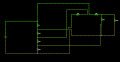
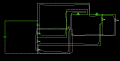
Edit: I have a go at connecting my circuit, I've attached a picture. Screenshot (2367).png The voltage is pretty close to what it should be, but I'm having problems connecting the output to that last grey wire, because I create a wire loop, and the circuit stops flowing. Do I need to have an output for that grey wire? Also, is it correct that I have not put a wire between the two inputs? If you want to see how the current flows the circuit is here: http://tinyurl.com/n6yvz97
 
Last edited:

WBahn

Joined Mar 31, 2012
33,126
This all looks correct, except are you sure you want R2 > R3? Ideally don't you want a voltage drop of 1.63 V across R2 and a drop of 2.37 V across R3?

That grey stub up to the 50 kΩ resistor is part of the same node as the bottom resistor; the fact that the simulator gets picky about illegal loops is a simulator artifact. You could route the wire up, over a bit, and down again just like you did the wire going to where the negative terminal of the 8 V battery was.

I'm not sure what you mean by putting a wire between the two inputs. What two inputs?

These values might be close enough, but I think I you can probably get quite a bit closer with a bit more effort.

The easiest way to do that is with a spreadsheet. Set up a column of cells that let you enter the value of R1 and that then calculates the ideal values of the other resistors. Then have a column next to that where you can enter the actual values of the effective resistors you make using simple combinations of available resistors. Have the next column calculate the unloaded voltages at the divider outputs (assume that you have enough current so that the loaded voltages are close). Then make up a table of all of the combinations of resistances you can get with simple series-parallel combinations of the available resistors so that it is easy to choose combinations that are close to what you want.

Go for the low hanging fruit first and make a table (in the spreadsheet) of the parallel combination of any two resistors from your list of ten values available. This can be done, literally, in less than two minutes.

For instance, from your prior post you need:

R1 = 0.84 * R4
R2 = 0.41 * R4
R3 = 0.53 * R4

You can carry more sig figs in your spreadsheet, but two sig figs would put you into the few percent range, which should be more than enough if you can get it.

So if you choose R4 to be 1 kΩ, you need 840 Ω, a 410 Ω, and a 530 Ω resistors.

From the table of parallel resistor combinations we can see (I can, you need to make the table) that we can combine two resistors to get 833 Ω, 412 Ω, and 519 Ω. The worst of these is right at 2% off from the ideal value. That is more than close enough since the effect of loading will be quite a bit more than that (meaning that to get this close in actuality you need to actually calculate the loaded voltages on those nodes, which wouldn't be too difficult to do, but probably not worth it).
 

Thread Starter

Purple_Letters

Joined Apr 24, 2017
20
This all looks correct, except are you sure you want R2 > R3? Ideally don't you want a voltage drop of 1.63 V across R2 and a drop of 2.37 V across R3?

That grey stub up to the 50 kΩ resistor is part of the same node as the bottom resistor; the fact that the simulator gets picky about illegal loops is a simulator artifact. You could route the wire up, over a bit, and down again just like you did the wire going to where the negative terminal of the 8 V battery was.

I'm not sure what you mean by putting a wire between the two inputs. What two inputs?

These values might be close enough, but I think I you can probably get quite a bit closer with a bit more effort.

The easiest way to do that is with a spreadsheet. Set up a column of cells that let you enter the value of R1 and that then calculates the ideal values of the other resistors. Then have a column next to that where you can enter the actual values of the effective resistors you make using simple combinations of available resistors. Have the next column calculate the unloaded voltages at the divider outputs (assume that you have enough current so that the loaded voltages are close). Then make up a table of all of the combinations of resistances you can get with simple series-parallel combinations of the available resistors so that it is easy to choose combinations that are close to what you want.

Go for the low hanging fruit first and make a table (in the spreadsheet) of the parallel combination of any two resistors from your list of ten values available. This can be done, literally, in less than two minutes.

For instance, from your prior post you need:

R1 = 0.84 * R4
R2 = 0.41 * R4
R3 = 0.53 * R4

You can carry more sig figs in your spreadsheet, but two sig figs would put you into the few percent range, which should be more than enough if you can get it.

So if you choose R4 to be 1 kΩ, you need 840 Ω, a 410 Ω, and a 530 Ω resistors.

From the table of parallel resistor combinations we can see (I can, you need to make the table) that we can combine two resistors to get 833 Ω, 412 Ω, and 519 Ω. The worst of these is right at 2% off from the ideal value. That is more than close enough since the effect of loading will be quite a bit more than that (meaning that to get this close in actuality you need to actually calculate the loaded voltages on those nodes, which wouldn't be too difficult to do, but probably not worth it).
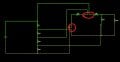
You have been amazingly helpful, thank you so much! When I said the inputs, I meant do I need to connect the areas I've circled (I'm pretty sure I don't but just want to double check):Screenshot (2367)_LI.jpg

If I swap R2 and R3, so that a smaller voltage drop occurs across R3, won't I have the wrong output voltage? Because the outputs are currently in descending order (11.4, 8, 6.37, 4) rather than 11.4, 6.37, 8, 4? I may be misunderstanding what you are trying to say.

I've also attached screenshots of my excel spreadsheet, and I don't seen to be getting the same values as you are? I don't have any resistances in the 800 ohms range?
 

Attachments

WBahn

Joined Mar 31, 2012
33,126
Across R2 (your 500 Ω) resistor, you ideally want (8 V - 6.37 V) = 1.67 V.
Across R3 (your 400 Ω) resistor, you ideally want (6.37 V - 4.0 V) = 2.37 V.

Since R2 and R3 have the same current (or close to it) flowing in them, shouldn't R2 be smaller than R3?

What is the parallel combination of a 1 kΩ resistor and a 5 kΩ resistor?

Look at the diagonal values in your table. Do they make sense?

What is 100 Ω in parallel with 100 Ω? What does your table say it is?

Does it make sense that the values on the 700 Ω row are less than the values either above or below them in several of the columns?

Get in the habit of asking sanity-check questions whenever you can. You are going to make a lot of mistakes -- we all do -- so you want to develop habits that let you catch most of them almost immediately.

If you copy the resistor values in across a row above the table, then you can set up a single equation for the top left cell, locking its data to the left most (row header) and top most (column header) cells as appropriate, and then copy that single cell to fill the entire table and you are done.
 

WBahn

Joined Mar 31, 2012
33,126
You have been amazingly helpful, thank you so much!
You are more than welcome -- you have shown a willingness to take advice and then do the hard work of trying to understand and use it; I'm more than willing to spend a lot of time helping someone with that kind of attitude.

When I said the inputs, I meant do I need to connect the areas I've circled (I'm pretty sure I don't but just want to double check)
Ah. Nope, you are correct. Your circuit is basically the following:

Edit_2017-04-25_1.png

Your 8 V supply is the stack consisting of R2, R3 and R4.

Your 5 V supply is the stack consisting of R1 and R2.

R2 has three currents flowing in it. The largest is the bias current for the voltage divider. The current flowing in the 8 V supply flows upward through R2 and out the junction of R1 and R2 while the current flowing in the 5 V supply flows upward through R2 and on into R1.

This concept actually provides a very simple way to take the circuit loading into affect. You write the nominal current in each of the divider resistors as the superposition of a downward bias current and upward supply currents for each supply that that resistor is a part of. The latter ones you know from the original analysis and the bias current is the same for all of them. This allows you to make only a very minor tweak to your spreadsheet to get nominal resistance values that take loading into account. As a result, you no longer have to keep the bias current an order of magnitude higher than the circuit currents to get your voltages close to the targets.

I would be tempted to use this approach to pick resistors that are comparable in size to the circuit resistors but that yield very close results. The instructor will likely see your choices and conclude that you didn't take loading into account and thus will get very poor results when you connect everything up. Then they will probably be at a loss when you show that the results are very close to the nominal values.[/QUOTE][/QUOTE]
 

Thread Starter

Purple_Letters

Joined Apr 24, 2017
20
Across R2 (your 500 Ω) resistor, you ideally want (8 V - 6.37 V) = 1.67 V.
Across R3 (your 400 Ω) resistor, you ideally want (6.37 V - 4.0 V) = 2.37 V.

Since R2 and R3 have the same current (or close to it) flowing in them, shouldn't R2 be smaller than R3?

What is the parallel combination of a 1 kΩ resistor and a 5 kΩ resistor?

Look at the diagonal values in your table. Do they make sense?

What is 100 Ω in parallel with 100 Ω? What does your table say it is?

Does it make sense that the values on the 700 Ω row are less than the values either above or below them in several of the columns?

Get in the habit of asking sanity-check questions whenever you can. You are going to make a lot of mistakes -- we all do -- so you want to develop habits that let you catch most of them almost immediately.

If you copy the resistor values in across a row above the table, then you can set up a single equation for the top left cell, locking its data to the left most (row header) and top most (column header) cells as appropriate, and then copy that single cell to fill the entire table and you are done.
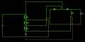
Ok, I've recalculated my resistors, so R2=410 ohms and R3=590 ohms. I've also fixed my excel calculations, and put the parallel resistor combinations into my circuit. The combination for R3=590 ohms isn't particularly accurate (614 ohms), but I think it will be too fiddly to put three resistors in parallel, considering we have to build this in a limited time frame and it is already quite complication for me! This is my final circuit, please let me know if there's anything that looks wrong, and once again thank you so much for your help! You have no idea how grateful I am! Screenshot (2378).png
 

Thread Starter

Purple_Letters

Joined Apr 24, 2017
20
R2 has three currents flowing in it. The largest is the bias current for the voltage divider. The current flowing in the 8 V supply flows upward through R2 and out the junction of R1 and R2 while the current flowing in the 5 V supply flows upward through R2 and on into R1.

This concept actually provides a very simple way to take the circuit loading into affect. You write the nominal current in each of the divider resistors as the superposition of a downward bias current and upward supply currents for each supply that that resistor is a part of. The latter ones you know from the original analysis and the bias current is the same for all of them. This allows you to make only a very minor tweak to your spreadsheet to get nominal resistance values that take loading into account. As a result, you no longer have to keep the bias current an order of magnitude higher than the circuit currents to get your voltages close to the targets.

I would be tempted to use this approach to pick resistors that are comparable in size to the circuit resistors but that yield very close results. The instructor will likely see your choices and conclude that you didn't take loading into account and thus will get very poor results when you connect everything up. Then they will probably be at a loss when you show that the results are very close to the nominal values.
Once again (haha), I'm really confused by what you are saying here? Is this important to apply to my circuit? The current is above the minimum 1.6 mA that I calculated before, and as long as the circuit functions, I think I will get full credit for the experimental part (this is only a first year assignment and our first week studying electronics).
 

WBahn

Joined Mar 31, 2012
33,126
Don't box yourself into thinking you can only use parallel combinations. Do you see an easy way to use two resistors to get something that is a lot closer to 590 Ω than 614 Ω is?

But even 614 Ω is closer than is justified given that loading wasn't taken into account (beyond setting the current in the divider high enough so that it shouldn't be a big issue).

You might hedge your bets and come up with a set of resistor values on the assumption that you only have one of each kind of resistor available (which means that you need to assume that the resistors in the original circuit don't have to be constructed out of your set of resistors).

I think you are going to do great on this lab, particularly if you understand things well enough to start from scratch with a similar problem and work it through.
 

WBahn

Joined Mar 31, 2012
33,126
Once again (haha), I'm really confused by what you are saying here? Is this important to apply to my circuit? The current is above the minimum 1.6 mA that I calculated before, and as long as the circuit functions, I think I will get full credit for the experimental part (this is only a first year assignment and our first week studying electronics).
Don't worry about it. I think you are going to do better than most of your peers.

I think this is a really good lab project, but it seems a bit much for a first week into this material, so I suspect a lot of people are just going to get tanked -- which may be the goal; often times the most effective learning experiences are when you fight with something and fail only to have a relatively simple approach shown to you afterward.

If I get a chance later I will walk you through what I was talking about. But I'll wait until after you do your lab and get the results -- please let us know how it goes.
 
Top