Facebook
 Google
 GitHub
 Linkedin
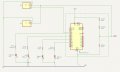
Hi - I made a voltage divider circuit to 'make' 5 V dc from 12V. I tested it on the bench and got the 5v I was looking for. When I installed it sourcing 12v, I only got 3.5v. When it was installed, I did not attach any loads or sensors to it. Just power. The only difference between the installed location and the bench was the power supplies. I'm guessing there is something going on there but I don't understand since the sourced voltage is the same - 12 V in both locations. Any ideas on why I would see a voltage drop would be appreciated. Thanks.
Voltage Divider
- Thread starter Jibebuoy
- Start date