Facebook
 Google
 GitHub
 Linkedin
 Hi everyone!
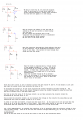
In this circuit ive been given the values; R1:650kohm. R2:325kohm, Vcc:15v, Re: 0. beta=100
The question is calculate Ic and find out if the amplifier is in active mode.
I^ve calculated Vr2 to be 5 volt. And thus Vb= 5v.. When calculating Ir1 with (Vcc-Vb)/R1 and Ir2 with Vb/R2, I get Ib=Ir1-Ir2=0. Thus Ic is 0 through Ic=Ib*beta. In the next partquestion I`m being asked to calculate Ic with another beta-value, so I guess my reasoning has been wrong. Can somebody tell me why what I`ve done so far is wrong?
Thanks in advance!


")