Need help with voltage divider circuit

Thread Starter

BuzzTronic

Joined May 5, 2018
12
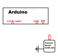
hi, see attached. I need some assistance with this. The sensor is 0-240 ohms based on pressure, I need that to become 0-5 volts at the Arduino input.

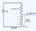
I know that I need a resistor somewhere and the sensor is the other resistor. I just cant seem to work out the details. The senor will connect to the input pin. And the 5vdc goes into that but where is the other resistor? And what should the value be?

Also, how much current will flow because I will need to limit that ui would think.
Thank U
 

Attachments

WBahn

Joined Mar 31, 2012
32,706
You aren't going to get the full 0 V to 5 V range starting with a 5 V supply rail using a voltage divider. They call it a voltage divider for a reason.

How much current is the pressure sensor intended to take?

How linear do you need the relationship between the voltage at the Arduino input and the resistance to be? Do you know what the relationship is, and how linear it is, between pressure and resistance?
 

Thread Starter

BuzzTronic

Joined May 5, 2018
12
Hi guys, I partially worked it out using an online voltage divider calculator. I dont know about the current though. Thats the remaining question. Crutschow, the oil pressure sender body is grounded to the engine by being screwed into it. (This is an old school oil pressure sender). It's OHMS varies from around 245ohms at zero pressure, to 30 ohms at 180 psi, but this gauge Im making only reads 0-80, and the engine probably wont exceed 60psi anyway.

I made a table of pressures to ohms by applying air pressure to the sender and measuring its resistance:
10psi=180 ohms
20psi = 168 ohms
40psi=108 ohms
50psi= 98ohms
60psi= 81 ohms
80psi= 40ohms

Using the calculator, I determined that a 180ohm resistor1 would work. The sending unit is resistor2. I adjusted the arduino program's min/max voltages to get 10psi where it needs to be on the stepper motor, and also 80psi. at 50psi (using 100ohm resistor) the gauge reads just over 40 but thats okay. In order to really calibrate it would require a rewrite of the program and I used ChatGPT, so Im lucky it even works this good. If I ask for a table in the program, chatGPT would probably break it!

Im happy so far, but not sure how much current is moving back into the arduino input pin. is there a way to determine that? I dont want it to cook or anything. (Sorry Im a noob at this stuff)

I attached the circuit Im using.
 

Attachments

MrChips

Joined Oct 2, 2009
34,629
Simple. You can look up the datasheet of the MCU used in the Arduino.

Another simple method is to measure the voltage at the sensor output.
Now, disconnect the Arduino input and measure again.
What two voltage readings do you measure?
 

WBahn

Joined Mar 31, 2012
32,706
Hi guys, I partially worked it out using an online voltage divider calculator. I dont know about the current though. Thats the remaining question. Crutschow, the oil pressure sender body is grounded to the engine by being screwed into it. (This is an old school oil pressure sender). It's OHMS varies from around 245ohms at zero pressure, to 30 ohms at 180 psi, but this gauge Im making only reads 0-80, and the engine probably wont exceed 60psi anyway.

I made a table of pressures to ohms by applying air pressure to the sender and measuring its resistance:
10psi=180 ohms
20psi = 168 ohms
40psi=108 ohms
50psi= 98ohms
60psi= 81 ohms
80psi= 40ohms

Using the calculator, I determined that a 180ohm resistor1 would work. The sending unit is resistor2. I adjusted the arduino program's min/max voltages to get 10psi where it needs to be on the stepper motor, and also 80psi. at 50psi (using 100ohm resistor) the gauge reads just over 40 but thats okay. In order to really calibrate it would require a rewrite of the program and I used ChatGPT, so Im lucky it even works this good. If I ask for a table in the program, chatGPT would probably break it!

Im happy so far, but not sure how much current is moving back into the arduino input pin. is there a way to determine that? I dont want it to cook or anything. (Sorry Im a noob at this stuff)

I attached the circuit Im using.
That pressure gauge appears to be pretty nonlinear at low pressure but not too bad over most of the range.
1741846377815.png
Since you are using an MCU, this is not much of a concern as you can calibrate it in software as long as it is sufficiently repeatable.

If you want to pick a resistor so that two points produce nominal voltages at the Arduino input pin, a simple divider won't do it because you are trying to control two data points with only one variable (the value of the fixed resistor).

But it is easy to plot the output voltage at your two endpoints (10 psi and 80 psi) as a function of Ro (the fixed resistor) so that you can pick a value of Ro that seems like a reasonable compromise.

The output of the divider, assuming a nice, constant Vcc (power supply to the divider), is

Vout = Vcc (R / (Ro + R))


1741847725149.png

Your biggest span appears to be when Ro is about 100 Ω.

As for your question about the current -- you will need to put enough current into the sensor to get the voltage where you need it. With 100 Ω, you max current (at 80 psi) will be about

Imax = 5 V / (40 Ω + 100 Ω) = ~36 mA

This has no bearing on how much current the input of the Arduino will see. This should be a pretty high impedance input designed to have any voltage over its specified operating range applied directly to the pin. The concern would come in if that current (which you can get from the data sheet) is more than about 10% of the current flowing through the divider. Since the input current is likely going to be in the microamp range (or less), this is not a factor in your case.
 

LowQCab

Joined Nov 6, 2012
5,101
The easiest solution is to simply obtain a modern General-Motors Oil-Pressure-Sensor.

It is specifically designed to run on Ground and ~5-Volts+,
and the "Low-Impedance-Output" eliminates Noise problems,
and is specifically designed to drive a Computer-Input with a common, standardized, 0.5V to 4.5V Signal.
( which is also the Voltage-Range that most "aftermarket-Gauges" use )
( You can get one of these Sensors at your local Junk-Yard basically for "Free", including the Wiring-Pig-Tail/Connector ).

A precise Graph of the Pressure vs Voltage-Output, and the Pin-Out of the Sensor is easily obtainable.
These Sensors have around ~2% accuracy, which is excellent for a cheap Sensor.
See the PDF below.
..
.
.
 

Attachments

Last edited:

Thread Starter

BuzzTronic

Joined May 5, 2018
12
lowq, why didnt I think of that! I will order one even though this is now functional enough for my project. anyway thanks for all the replies. I do this mainly to learn, but the gauge will be used in an antique boat project.
 

LowQCab

Joined Nov 6, 2012
5,101
No, I have no clue about the part-number of the Sensor.
The Part-number of the Pig-Tail-Plug is in my attached PDF-file.
I'm guessing maybe You live in a Country other than the USA,
here there are millions of them available used, dirt-cheap.
If I were to make a wild-guess,
any GM 4.8L or 5.3L V-8 built in the 2000's, ( LS & LT-Engines ), use the same part-number-Sensor.
Any competent Auto-Parts-Store-Man should be able to figure-out what You need.
( some of them are definitely NOT competent, some of them are absolute geniuses )

The Temp-Sensors, (( IAT (Intake-Air-Temp) and, CLT (Coolant-Temp Sensors )),
use the same internals and Voltages, but they have unique 3-Pin-Plugs depending on their function.

You "may" need a Threaded-Brass-Adapter depending on the size of the hole you're installing it in,
most older Engines use a !/2"-NPT threaded-hole,
newer Engines usually use 1/4"-NPT threaded-hole.
.
.
.
 
Last edited:
If the 5V Vcc is stabilised (probably does) a simple current source like below is quite precise/constant. Comparing to your resistors divider approach this solution uses the 5V Vcc range much effectively and gives you better resolution.
The constant 15mA current source supplying the sensor produces the following output:

0 ohm…0V
50 ohm…0.75V
100 ohm…1.5V
150 ohm…2.25V
200 ohm…3V
250 ohm…3.75V

You can see the Rsensor vs. Vout relation is linear.

IMG_1700.jpeg
 
Last edited:

Thread Starter

BuzzTronic

Joined May 5, 2018
12
No, I have no clue about the part-number of the Sensor.
The Part-number of the Pig-Tail-Plug is in my attached PDF-file.
I'm guessing maybe You live in a Country other than the USA,
here there are millions of them available used, dirt-cheap.
If I were to make a wild-guess,
any GM 4.8L or 5.3L V-8 built in the 2000's, ( LS & LT-Engines ), use the same part-number-Sensor.
Any competent Auto-Parts-Store-Man should be able to figure-out what You need.
( some of them are definitely NOT competent, some of them are absolute geniuses )

The Temp-Sensors, (( IAT (Intake-Air-Temp) and, CLT (Coolant-Temp Sensors )),
use the same internals and Voltages, but they have unique 3-Pin-Plugs depending on their function.

You "may" need a Threaded-Brass-Adapter depending on the size of the hole you're installing it in,
most older Engines use a !/2"-NPT Threaded-hole,
newer Engines usually use 1/4"-NPT threaded-hole.
.
.
.

Thanks I do live in the USA, and my best friend owns a smallish auto salvage yard. Your list of vehicles really helps. This is going into a Kubota diesel which uses BSPT, believe it or not, but I have an adapter to NPT. I would imagine a GM part would be NPT.

I really appreciate the suggestion, this looks like it will be way more accurate/predictable.
 

Thread Starter

BuzzTronic

Joined May 5, 2018
12
I bought this sensor. And the pigtail connector. Now I dont know which pin is 5v in, signal out, and ground. I THINK I found that the single pin is signal out. I could find the info no place. I even asked chatGPT to search to no avail. If anyone is better at searching the googles or interwebs than I am, please help. Meanwhile I have some fittings coming to set this up with a gauge and a tire stem so I can apply pressure and check the output volts, and also some fittings to adapt this to the engine. This sensor has M16-1.5 threads, and the engine oil pressure sender port is 1/8" BSPT, so the correct adapters are coming. Just need to determine the pinouts. I dont know if accidentallly reversing the voltage would fry it. The sensor is a GM Part 12674782.

https://www.amazon.com/dp/B01M3VA9HM
 

LowQCab

Joined Nov 6, 2012
5,101
I provided a PDF for reference to the Pin-Out.

If You had gotten the Sensor from a Junk-Yard, it would have come with color-coded-wires.

If You hook it up wrong, or apply more than ~5-Volts, You will instantly smoke it.

~$30.oo sounds like full retail price,
but of course I haven't looked in a long time,
and at least it's a new AC-Delco part..
.
.
.
 

Thread Starter

BuzzTronic

Joined May 5, 2018
12
I provided a PDF for reference to the Pin-Out.
If You had gotten the Sensor from a Junk-Yard, it would have come with color-coded-wires.
If You hook it up wrong, or apply more than ~5-Volts, You will instantly smoke it.
thanks, OK thats for the connector side. I will go with that, thanks! My friend owns a junkyard so my price would be free, BUT he just scrapped out many cars, and I would have to see whats left, find the oil sensor, and remove it. Amazon had the new ACDelco one and the pigtail (which has different color wires but now that doesnt matter). INa few days i will have the test plumbing to hook this up and apply air pressure, while I feed 5v and read the output. Once thats done, I can hook it to the arduino/ gauge and watch the needle move with the application of pressure. I'll post a video. This was such a good suggestion I cant thank u enough. As u can see, I get concepts pretty good but not great at figuring everything out. But now this one is probably "in the bag" as they say...
 

Thread Starter

BuzzTronic

Joined May 5, 2018
12
Just a followup. Got the GM oil pressure sensor, the thread adapters (M14-1.5) and some plumbing and ran some air pressure tests. The wiring was a bitch, because the pinout diagram does not make it clear which side is shown. The 3rd pin is easy, thats the output. But the other two I had backwards initially. Didnt harm it though. Once the hookup was established the response is nice, starting at .5v at zero psi, and increasing about .3v per 10psi. This is a much more elegant solution and as LowQCab mentioned, much more appropriate for the task at hand. Heres an exciting test video (was too lazy to add a pressure regulator and was trying to stabilize the pressure with a hand held tire inflator)
 

Thread Starter

BuzzTronic

Joined May 5, 2018
12
I did it the right way. I could have bought a solution but it did not meet the aesthetic specs for the project. And, this is also, as I mentioned, a learning project. :)
 
Top