 Facebook
 Google
 GitHub
 Linkedin
I building a test box for a variety of Li-ion battery configurations (2S, 3S, 4S) to test different battery configurations for different loads. I am using a Raspberry Pi as the controller, and I need to sense if the test circuit is live or not. The test circuit can have anywhere from 0-5V (min charge for 2S config) to 16.8V (max charge for 4S configuration). I am using a GPIO pin on the Pi to sense the presence of a voltage on the test circuit - 0 to 3.3V max (2V - 3.3V is logic 1; 0V - 0.8V is logic 0), no more than 0.5mA source or sink, and a ~50K pull up or down resistor (configured in software). I am not measuring the voltage level, just producing a 0/1 result if the test circuit is live or not. There is also a 5V rail and a 3.3V rail available.
I don't have a lot of room on the board, so a simple resistor/3V Zener diode won't work as I would need a 3-4 Watt resistor for the 16.8 V test if I assume 20 mA for the 5V option. Thanks for any suggestions you may have on a simple circuit to determine if the test circuit is live.
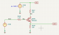
I came up with this circuit which seems to work based on the simulation and actually building the circuit and testing it on my bench. On the bench, I get a logic 1 from the GPIO pin when the input voltage is ~3V, which is OK, but I would rather have the logic 1 happen when the input voltage is lower. I would be interested in any suggestions to make the circuit more sensitive to lower voltages - i.e. increase the slope of the V3VC signal, but keep the plateau around 3V.
I don't have a lot of room on the board, so a simple resistor/3V Zener diode won't work as I would need a 3-4 Watt resistor for the 16.8 V test if I assume 20 mA for the 5V option. Thanks for any suggestions you may have on a simple circuit to determine if the test circuit is live.
I came up with this circuit which seems to work based on the simulation and actually building the circuit and testing it on my bench. On the bench, I get a logic 1 from the GPIO pin when the input voltage is ~3V, which is OK, but I would rather have the logic 1 happen when the input voltage is lower. I would be interested in any suggestions to make the circuit more sensitive to lower voltages - i.e. increase the slope of the V3VC signal, but keep the plateau around 3V.
Attachments
-
 158.1 KB Views: 7
 -
 12.7 KB Views: 7
Last edited:


