Voltage Divider with Three Outputs

Thread Starter

Purple_Letters

Joined Apr 24, 2017
20
I need to design a voltage divider circuit with three out puts of 8V, 5V and 4V, with an input voltage of up to 30V. I believe it should look something like this, and I think I would need to use the equation V(out)=V(in)*R/(R1+R2+R3+R4), but I don't know what to do beyond that as there is four variables? The materials list for the experiment is 1kΩ, 2kΩ, 5kΩ, 10kΩ, 100kΩ, 1MΩ resistors and 100, 200, 500 and 700Ω 5W resistors. I don't really understand the difference between these two?

Our lecturer has mentioned that this is an "un-physical" circuit, meaning it is not a feasible way to produce the needed voltages (due to a very high current I think?), however, I still need to show the mathematics to work out which resistors will produce the required voltages. Thanks in advance for any help!
 

JoeJester

Joined Apr 26, 2005
4,390
What you don't show is the loads and the power required by the loads. That design has been around forever.

There are disadvantages to it, but it is feasible. I've worked on supplies with that style dividers.

There were designed prior to your generation as there were prior to my generation.

In fact, R1 had two functions. I'm sure your teacher can name them both.....
 

Thread Starter

Purple_Letters

Joined Apr 24, 2017
20
What you don't show is the loads and the power required by the loads. That design has been around forever.

There are disadvantages to it, but it is feasible. I've worked on supplies with that style dividers.

There were designed prior to your generation as there were prior to my generation.

In fact, R1 had two functions. I'm sure your teacher can name them both.....
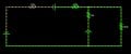
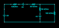
This is the circuit that the voltage divider needs to supply:
http://tinyurl.com/lffwrhw

purple_1.jpg

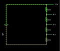
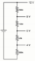
I've made some progress with the value of the resistors needed, to create this:
http://tinyurl.com/mhpxsw3

purple_2.jpg

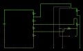
And now I'm struggling to connect the two, due to two issues: the load changes the voltage/current (but I think this is ok, as long as we explain why), and also because I cannot draw the complete circuit without creating a path with no resistors: http://tinyurl.com/losq3qv

purple_3.jpg

Moderators note : uploaded pictures to the forum
 
Last edited by a moderator:

Thread Starter

Purple_Letters

Joined Apr 24, 2017
20
In your equation for Vout, what is the R for each particular output voltage?

Are the higher values of resistance given as a different power rating, in Watts?
Sorry, I'm not too sure I understand your question? The R value is the unknown value of the resistance, however, I have managed to work this out (see my previous post) and now I'm struggling to connect the voltage divider to the other circuit?
 

WBahn

Joined Mar 31, 2012
32,801
What will the current be in the resistors?

What will the voltage be across R1?

What will V1 be?

What will the voltage be across R2?

What will V2 be?

And so on.

You will end up with four equations and three unknowns. That means that you get to arbitrarily pick one of the resistor values.

Do you have just one resistor of each of the values in your list, or can you use the same value more than once?

Are all of the resistor 5W, or just the last four in your list? If just the last four, what is the power rating of the others?
 

Thread Starter

Purple_Letters

Joined Apr 24, 2017
20
What will the current be in the resistors?

What will the voltage be across R1?

What will V1 be?

What will the voltage be across R2?

What will V2 be?

And so on.

You will end up with four equations and three unknowns. That means that you get to arbitrarily pick one of the resistor values.

Do you have just one resistor of each of the values in your list, or can you use the same value more than once?

Are all of the resistor 5W, or just the last four in your list? If just the last four, what is the power rating of the others?
The only information I have about the resistors is what I copied into my original post, some are 5W and the others are unspecified. I have no idea if I can use each resistor more than once.. I'm hoping we get multiple. I actually solved the resistance problem by using an initial voltage of 12 and working out the voltage drop to be 4:3:1:4, so I just used resistors in this ratio, with an initial resistor of 200k: http://tinyurl.com/kspy27c . However, I am not struggling to connect the voltage divider to my other circuit: http://tinyurl.com/lffwrhw . This is my progress so far, but I keep creating a "wire loop" where there is a path of no resistance: http://tinyurl.com/m5e3a54
 

WBahn

Joined Mar 31, 2012
32,801
This is the circuit that the voltage divider needs to supply:
http://tinyurl.com/lffwrhw
I have absolutely no clue how you are supposed to connect your voltage divider to that circuit? What are the connection points? What is it that the combination of the two circuits is supposed to achieve?

I've made some progress with the value of the resistors needed, to create this:
http://tinyurl.com/mhpxsw3
The original problem said that the supply was 30 V. It actually said "up to 30 V", which makes no sense because if you cut the supply voltage in half, then the (unloaded) outputs at each of the voltage taps will be reduced by half. A circuit like this is very dependent on a stable and fixed supply voltage (among other things).
 

Thread Starter

Purple_Letters

Joined Apr 24, 2017
20
I have absolutely no clue how you are supposed to connect your voltage divider to that circuit? What are the connection points? What is it that the combination of the two circuits is supposed to achieve?


The original problem said that the supply was 30 V. It actually said "up to 30 V", which makes no sense because if you cut the supply voltage in half, then the (unloaded) outputs at each of the voltage taps will be reduced by half. A circuit like this is very dependent on a stable and fixed supply voltage (among other things).
Our materials list says our voltage provider is capable of providing up to 30V.. it doesn't say anywhere what voltage we should use for the input (as we have other tests to do with the same equipment). I chose a lower voltage so I could use a smaller R1.

I have no idea what the combination of the two circuits is supposed to achieve.. It's more of a theoretical exercise I think? The outputs of the voltage divider are supposed to replace the three batteries (so that's the connection points I think?). How would you go about doing this? This is as close as I can get to making a working circuit: http://tinyurl.com/ml39jrq
 

WBahn

Joined Mar 31, 2012
32,801
Our materials list says our voltage provider is capable of providing up to 30V.. it doesn't say anywhere what voltage we should use for the input (as we have other tests to do with the same equipment). I chose a lower voltage so I could use a smaller R1.
Okay, I think I see. You have a variable voltage supply that you can use for your circuit and it can be set to any voltage up to 30 V but you get to pick the voltage it is set at. Makes sense.

How much current can it supply?

I have no idea what the combination of the two circuits is supposed to achieve.. It's more of a theoretical exercise I think? The outputs of the voltage divider are supposed to replace the three batteries (so that's the connection points I think?). How would you go about doing this? This is as close as I can get to making a working circuit: http://tinyurl.com/ml39jrq
I'll have to think about this a bit. I think I am picturing what the goal is. But I think you need to know what the values of the voltage sources in the target circuit are. Is that information given?

Also, it is much preferred that you upload your images to AAC instead of linking to a third-party site.
 

Thread Starter

Purple_Letters

Joined Apr 24, 2017
20
Okay, I think I see. You have a variable voltage supply that you can use for your circuit and it can be set to any voltage up to 30 V but you get to pick the voltage it is set at. Makes sense.

How much current can it supply?


I'll have to think about this a bit. I think I am picturing what the goal is. But I think you need to know what the values of the voltage sources in the target circuit are. Is that information given?

Also, it is much preferred that you upload your images to AAC instead of linking to a third-party site.
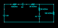
This picture of the circuit is the only information given. The power supply is described as "1 x 30V 3 Amp Variable power supply with fixed 12V and 5V outputs at 500 mA".
 

Attachments

dl324

Joined Mar 30, 2015
18,313
I need to design a voltage divider circuit with three out puts of 8V, 5V and 4V, with an input voltage of up to 30V
Without using something to regulate voltage, how can you get fixed outputs with an input voltage of "up to 30V"?

Something must be being lost in translation. Post the exact wording of the problem.

For future reference, it would be helpful for you to post images on this website. Use reasonable image sizes/resolutions.
 

Thread Starter

Purple_Letters

Joined Apr 24, 2017
20
Without using something to regulate voltage, how can you get fixed outputs with an input voltage of "up to 30V"?

Something must be being lost in translation. Post the exact wording of the problem.

For future reference, it would be helpful for you to post images on this website. Use reasonable image sizes/resolutions.
The exact problem is "The circuit (referring to the attached picture) requires 8V, 5V and 4V voltage sources. Design and simulate a voltage divider to provide this, using the source and resistors that you have. Integrate the power supply into the simulated circuit and observe and record its behavior in your notebook." The materials I have are (NB some of this is used for other tasks eg. providing ohms law, building all combinations of a three resistor circuit):
- 1kΩ, 2kΩ, 5kΩ, 10kΩ, 100kΩ, 1MΩ resistors
− 100, 200, 500 and 700Ω 5W resistors
− banana plug wire connectors
− 2 x handheld multimeters
− 1 x 30V 3 Amp Variable power supply with fixed 12V and 5V outputs at 500 mA
 

Attachments

dl324

Joined Mar 30, 2015
18,313
The exact problem is
This makes more sense. You have a 30V variable supply, but it doesn't have to vary. You are given the resistors values you need to use to provide the 3 output voltages.

What does the schematic you posted have to do with the problem? You show "sources" of 4V, 5V, and 8V in the same circuit, but you can't get them simultaneously from the power supply you were given.
 

Thread Starter

Purple_Letters

Joined Apr 24, 2017
20
This makes more sense. You have a 30V variable supply, but it doesn't have to vary. You are given the resistors values you need to use to provide the 3 output voltages.

What does the schematic you posted have to do with the problem? You show "sources" of 4V, 5V, and 8V in the same circuit, but you can't get them simultaneously from the power supply you were given.
That is the only information I have... Anything else I say is just my interpretation of the task. I don't know why the source has sources/batteries which need to be replaced by a voltage divider. The schematic is just the circuit that the lecturer wants us to connect to this voltage divider.
 

dl324

Joined Mar 30, 2015
18,313
That is the only information I have... Anything else I say is just my interpretation of the task. I don't know why the source has sources/batteries which need to be replaced by a voltage divider.
You can ask clarifying questions for anything you don't understand.

See if you can design a 3 resistor voltage divider that will give the desired voltages. If you can't, then there's some missing information.
 

Thread Starter

Purple_Letters

Joined Apr 24, 2017
20
You can ask clarifying questions for anything you don't understand.

See if you can design a 3 resistor voltage divider that will give the desired voltages. If you can't, then there's some missing information.
I've created this: http://tinyurl.com/kspy27c does that look correct? The main thing I am struggling with now is how to connect it to my target circuit (the schematic I posted earlier).
 

dl324

Joined Mar 30, 2015
18,313

WBahn

Joined Mar 31, 2012
32,801
This picture of the circuit is the only information given. The power supply is described as "1 x 30V 3 Amp Variable power supply with fixed 12V and 5V outputs at 500 mA".
THIS makes a LOT more sense. Notice that the circuit you posted here has values for the supplies, while your previous version of this circuit did not. Makes ALL the difference!

Also, the polarities of some of the supplies in the earlier picture are reversed from what you show here. These make much more sense.

You want to create a voltage divider that outputs multiple voltages such that you can tie the appropriate nodes in the divider to the corresponding nodes in the circuit and have the resulting node voltages and branch currents in the circuit be unaffected (or only mildly so).

So first you need to decide how to integrate your voltage divider circuit into the other circuit so that you can remove all of the batteries. Then you need to decide what the voltages need to be at each of the voltage divider taps -- these will NOT just be battery voltages, but instead the voltages at the corresponding nodes in the original circuit. So you have to analyze the original circuit. Then you are in a position to calculate the ratios of the resistors in the divider. Then you are in a position to pick the value of one of them in order to simultaneously not exceed the current capabilities of your supply AND not exceed the power ratings of any of your resistors.

I think you need to use the large valued resistors to build the resistors in the original circuit. The other resistors, with the power ratings, are available to construct the voltage divider.
 

WBahn

Joined Mar 31, 2012
32,801
I've created this: http://tinyurl.com/kspy27c does that look correct? The main thing I am struggling with now is how to connect it to my target circuit (the schematic I posted earlier).
No, it is not correct. Those are not the voltages you need. You also need to use resistor values that are much smaller than the resistances in the original circuit.

Forget about the voltage divider for a moment. Analyze the original circuit and figure out the voltages at each node and the currents in each branch. THAT is your starting point.
 
Top