OK, 3 pairs. That could be 3 sets of windings (coils). Now what test equipment do you have? DMM, Scope? You can place a DMM across one set of leads, Set it to measure AC Volts and give the motor a spin and see if the meter does anything.
The problem is not knowing what does what. I have a small motor laying here from a CD / DVD player. Looking at it I can figure out I have three lines to the coils (3 phases) and 6 lines which go to three hall effect sensors. All of these things can be configured different depending on what the lines do and things like leads for sensors. I have a few old VCRs laying around that I was going to trash, I should rip one apart and check out the motor. Without actually seeing what you have it's about impossible to guess what lines do what.
The problem is not knowing what does what. I have a small motor laying here from a CD / DVD player. Looking at it I can figure out I have three lines to the coils (3 phases) and 6 lines which go to three hall effect sensors. All of these things can be configured different depending on what the lines do and things like leads for sensors. I have a few old VCRs laying around that I was going to trash, I should rip one apart and check out the motor. Without actually seeing what you have it's about impossible to guess what lines do what.
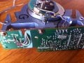
ok, forget those wires from before, , directly From the coils I have Pink , white , grey, red. tried to connect in many ways , got nothing out , think about how exactly they have to be connected and do I need anything extra . thank you for your help.
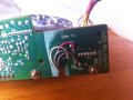
And will I be needing this sensor, it has 4 wires as well. it's all still on the circuit board together. i will send picture.
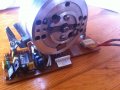
Well we know you are trying to make a small generator out of a old VCR tape head motor. After that we have no idea what you are spinning it with or how fast or what all you have still connected or disconnected from the actual windings.
Well we know you are trying to make a small generator out of a old VCR tape head motor. After that we have no idea what you are spinning it with or how fast or what all you have still connected or disconnected from the actual windings.
I'm just trying t make this motor give something out, i/m still spinning it with hand. must give me something out if it can work as a generator . i will be happy with 0000,1. must give me something .
do pictures help ?
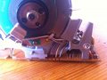
I may be wrong, but if i drill the magnet housing on this motor and I put stronger magnets in. will that help generating more per revolution ? magnets on this kind of motors seem to be very weak. and besides that,, i still can't find where does generated el. exits . oh .. brush.
I have not personally delved into those motors, But anytime a magnet crosses a coil it generates a voltage. You must have something not quite connected correctly. Even the stepper motor types generate.
Just Google Wind Generator from VCR motor, you will get rafts of examples!!
Max.
I had a career that spanned half a century and never encountered a VCR motor as a component. Since most of the VCR's and their motors were designed in Asia starting in about 1978, it hardly surprises me that few, if any, US engineers, including myself, have ever considered one of them as a component.
I have not personally delved into those motors, But anytime a magnet crosses a coil it generates a voltage. You must have something not quite connected correctly. Even the stepper motor types generate.
Just Google Wind Generator from VCR motor, you will get rafts of examples!!
Max.
Tape head motors are very weak electric motors to begin with so using them as a generator is going to be near useless for most anything practical other than maybe getting a few LED's to light up.
The simplest way to make one work would be to remove the circuit board and all of its connections to the motor and then connect the four leads coming from the motor coils to eight germanium diodes with two diodes on each lead. One going from negative to the lead and the second one from the lead to the positive for each of the four leads.
After that find a way to spin it up to high speed and you will get some power from it. Maybe 1 - 2 volts per 1000 RPM.
Personally if you want to make electrical power a tape head motor is one of the least efficient or favorable to use being most every other motor in a VCR can easily out perform it as a simple generator.
ok this was all helpful, thank' you gentlemen's I know i'm doing something wrong , the thing is i don't know what . ok, so Diodes.. I will try to do that. not happy with the speed needed but can i change that by installing stronger magnets on magnet housing ?
I have not personally delved into those motors, But anytime a magnet crosses a coil it generates a voltage. You must have something not quite connected correctly. Even the stepper motor types generate.
Just Google Wind Generator from VCR motor, you will get rafts of examples!!
Max.
You need to unsolder the wires from the circuit board to test.
Then you need to connect one pair of wires to the input of an oscilloscope to view the waveform.
 Facebook
 Google
 GitHub
 Linkedin
")