Facebook
 Google
 GitHub
 Linkedin
MisterBill2
- Joined Jan 23, 2018
- 27,684
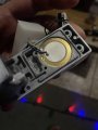
It seems to me that the internal is not "just a beeper". Consider the TS statement: "I check that the blue and yellow cables to the piezo speaker, while the red and black cables come from the battery. The switch that is activated with the lock is located on the black cable. " So is it likely to have TWO noise-makers???IMO:
The inductor is just an inductor; no other function. With three leads, it could be part of a flyback autotransformer voltage-boosted driver for the piezo element.
The piezo is just a beeper element, nothing else. As a motion detector, it is not a good one; it produces zero output in two of the three motion axes.
There are too many parts on the bottom of the board for just a piezo driver. If you are sure there is no other motion sensor or electronic assembly elsewhere in the device, then the IC probably is the sensor. I'd look around for a mercury switch tilt detector.
ak
The problem I see is that getting more sound requires more power. Boosting efficiency could possibly benefit, but that would require understanding the present circuit, which we do not actually see.