 Facebook
 Google
 GitHub
 Linkedin
Hello,
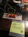
I want to build this phase control circuit using antiparallel SCRs to control the speed of a permanent split capacitor motor.
I think I understand its operation except I'm confused about the zener, if I'm thinking about this right it should be the other way round, so once the capacitor reaches its breakdown voltage it dumps into the primary of the pulse transformer.
Wondering if someone can help clear things up for me.
Thanks in advance!

")


