Facebook
 Google
 GitHub
 Linkedin
Hi Everyone
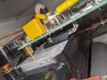
I was wondering if someone could help me understand this circuit which is the power control board from an electric boiler.
The manufactures technical support team reported that their triac board exhibits often high levels of earth leakage but that this is normal.This happens to be an issues for this particular boiler which I am not too happy about ( 100ma). On looking at the board I cannot see where there would be a leakage to earth from. I suspect they may have been talking about leakage through the triac from live to neutral which I understand is normal for this type of semiconductor.
Anyway I would like to understand the circuit better and get some opinions on how this specific board works.
My current understanding as follows:

Three triac circuit each with a rc snubber circuit and connected to two opto-couplers each. One which is driving the gate and the other one picking up the start of the phase to aid the micro-controller in correctly timing the gate signal for throttling?
I cannot see any ground connections in the circuit as I would expect all power is going between live and neutral. As the control side of the board is also opto-isolated, The only ground connection I could think of would be through the body of the triac which is bolted to a heat-sink.
Is the above understanding of the circuit correct of have I misunderstood how traics work and if so could someone explain how the manufacturers claims can be correct ?
Any thoughts of the above would be much appreciated and thanks for your time.
Regards
Nick
I was wondering if someone could help me understand this circuit which is the power control board from an electric boiler.
The manufactures technical support team reported that their triac board exhibits often high levels of earth leakage but that this is normal.This happens to be an issues for this particular boiler which I am not too happy about ( 100ma). On looking at the board I cannot see where there would be a leakage to earth from. I suspect they may have been talking about leakage through the triac from live to neutral which I understand is normal for this type of semiconductor.
Anyway I would like to understand the circuit better and get some opinions on how this specific board works.
My current understanding as follows:
Three triac circuit each with a rc snubber circuit and connected to two opto-couplers each. One which is driving the gate and the other one picking up the start of the phase to aid the micro-controller in correctly timing the gate signal for throttling?
I cannot see any ground connections in the circuit as I would expect all power is going between live and neutral. As the control side of the board is also opto-isolated, The only ground connection I could think of would be through the body of the triac which is bolted to a heat-sink.
Is the above understanding of the circuit correct of have I misunderstood how traics work and if so could someone explain how the manufacturers claims can be correct ?
Any thoughts of the above would be much appreciated and thanks for your time.
Regards
Nick