 Facebook
 Google
 GitHub
 Linkedin
Dear all,
I’m reaching out for some advice regarding an issue with a Niko ( belgian brand) home automation touchscreen. This screen controls parts of our smart home system, but unfortunately, it has stopped functioning properly. The screen keeps cycling on and off repeatedly, making the device unusable. It wants to boot but the power keeps toggling.
The unit is powered by a 24V DC external power supply, which I have tested and confirmed to be working correctly. So the issue appears to be internal to the touchscreen itself.
I have some basic knowledge of electronics — still a beginner, but very eager to learn more.
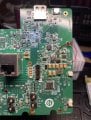
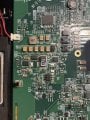
After opening the touchscreen, I noticed that a choke 4R7 on the board becomes extremely hot, nearly glowing, and emits a burnt smell. I don’t have access to any schematics, which makes troubleshooting more difficult.
Here’s what I’ve observed:
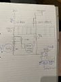
I’ve drawn a rough schematic of the components surrounding the choke not the whole board because it is complex board. However, there’s one surface-mount component I can’t identify. Its marking reads:
“942 LGSN N095”
It has 5 pins on the left and right sides, and 4 pins on the top and bottom, arranged in a square shape.
Would anyone be able to help identify this component? Or provide some insights into how this part of the circuit works — and what might be causing the choke to overheat and the power to cycle or some directions
Many thanks in advance!
Kenny
I’m reaching out for some advice regarding an issue with a Niko ( belgian brand) home automation touchscreen. This screen controls parts of our smart home system, but unfortunately, it has stopped functioning properly. The screen keeps cycling on and off repeatedly, making the device unusable. It wants to boot but the power keeps toggling.
The unit is powered by a 24V DC external power supply, which I have tested and confirmed to be working correctly. So the issue appears to be internal to the touchscreen itself.
I have some basic knowledge of electronics — still a beginner, but very eager to learn more.
After opening the touchscreen, I noticed that a choke 4R7 on the board becomes extremely hot, nearly glowing, and emits a burnt smell. I don’t have access to any schematics, which makes troubleshooting more difficult.
Here’s what I’ve observed:
- One side of the choke sits at 24V (from the power input).
- The other side is at 0V and is connected to the source of a MOSFET.
I’ve drawn a rough schematic of the components surrounding the choke not the whole board because it is complex board. However, there’s one surface-mount component I can’t identify. Its marking reads:
“942 LGSN N095”
It has 5 pins on the left and right sides, and 4 pins on the top and bottom, arranged in a square shape.
Would anyone be able to help identify this component? Or provide some insights into how this part of the circuit works — and what might be causing the choke to overheat and the power to cycle or some directions
Many thanks in advance!
Kenny
Attachments
-
 878.7 KB Views: 16
 -
 1.7 MB Views: 16
 -
 2.1 MB Views: 16


