Facebook
 Google
 GitHub
 Linkedin
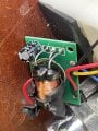
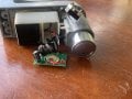
Hello. I'm new to the forum. I'm trying to understand this circuit from a disc locker for scooters. It is powered by a pack of 6 LR44 batteries, it has a speaker, and I guess the black ic is an accelerometer. But, maybe you help me to understand it better?. Thanks in advance.