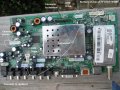
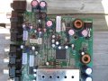
hey. check out the pictures of main board. i don't have any of those screws in right now. could that be why its not showing picture. just white screen. because needs screws in to complete circuit. there are four screws
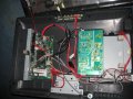
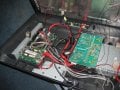
ok now i did not mount them properly (didn't place screws in). but that is where the boards would go. and there is only one proper position to put every cable in so i know i have everything hooked up right.
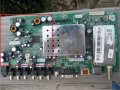
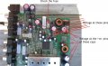
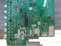
I want to u mark a fresh second picture like the one shown here.
Not the arrows, get me the voltages.
Meter negative should be grounded for every measurement.
When taking capacitor voltage, you can measure at both pins of the cap.
Note that all the voltage are DC and will be below 25V DC.
replaced the fuse. there are no voltages anywhere except at the diode the voltage started from some number don't remember then decreases all way to 0.2 or somewhere that low. so board isn't getting any voltages. not even at the fuse. i don't know where to put black probe. i put it on the ground from the cable from the power supply to main board. i even put black probe on one side of fuse and other on other side. nothing. but passes continuity with new one.
yes that is it and 12 DCV at main board both 12V pins. tv doesn't turn on anymore either. first worked with maroon tint. then just was white blank screen. and now doesn't turn on. no voltages anywhere on main board. besides the 12V pins. no voltage on 5VSB one
where does the voltage go first on main board. fuse. diode. etc????????
going around and probing around the board from either of the pins of fuse there is no continuity(black probe on one fuse pin. red going around components near fuse). but there is continuity between both fuse pins. resolder fuse in????
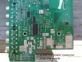
Look at the picture.
Disconnect power
Put the meter in resistance range, I want only 0Ω readings, to be sure.
Connect one probe permanently to the marking label 1 which is the 12V pins.
And use the other probe to measure the resistance at the other numbered points one by one. Which means only 1 probe will be moved between the markings
The last no.s is the jumpers.
You were right about the 12V pin. I got them wrong.
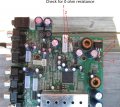
You need to find where the fuse has it's connection.
It should be to the supply.
disconnect the fuse and try to trace to where the fuse pins are connected.
Find for 0 ohms connection.
The connection to the fuse should be to those transistor or to a diode near by.
Try to trace it.
See the pic. Those are highly likely points that could be connected to the fuse.
If not, then try to find anything.
We need a connection from the 12V to any of those points.
man. that fuse leads to nowhere. tried and tried and tried. that was actually my first solder job that fuse. so of course. knowing me. the copper traces came off. i got way better now though especially with the solder pump. the solder wick was a little hard to use and always overheated the board by time started sucking up the solder due to my soldering gun.
what i usually do when no copper trace. is i will heat up higher on wire and holder solder near bottom and then work my way up and then let it drop down to the board by moving solder gun closer to bottom but never touching the board. that is how i did the bridge with the half missing part of the board. i did not put a copper wire like you told me and made sure i didn't burn board even more by only heating up higher on the wire.
so could it be the copper traces came off or something so the voltage isn't getting past fuse or even to the fuse????? cause when i checked voltages at fuse it was 0.
no continuity from 12v to fuse. which could be cause copper rings are gone. which could be why no voltage is getting anywhere. therefore there is no continuity from 12V to anywhere.
NOW THIS PIN (HAS NOTHING DIRECTLY OVER IT ON TOP SIDE, SO DON'T KNOW WHAT PIN IS FOR) WHICH IS CLOSE TO FUSE IN PICTURE SHOWS CONTINUITY TO POINTS EVEN ON OTHER SIDE OF BOARD. MAYBE EVERYWHERE ON BOARD. SO I THINK IT IS FUSE TRACES!
 Facebook
 Google
 GitHub
 Linkedin