troubleshooting a tv power supply

R!f@@

Joined Apr 2, 2009
10,004
So you are afraid of the glue....:rolleyes:


Ok.... with the FET removed.
New bridge installed
New slow blow 3.15A or 4A fuse installed
Give power and observe the fuse.
 

Thread Starter

johndoe45

Joined Jan 30, 2010
364
Lol. Just don't want to break another pin on a cap. That happened to me already and had to go to a store about thirty minutes from here for a 2 dollar cap. found a place closer now. but still. the cap messed up when resoldering in. trying to put pins through hole and they were already pretty bent and it broke. anyways. off topic

going to test it right now. can you tell when i edit a message? or want me to keep posting new posts???

FUSE IS GOOD
 

Thread Starter

johndoe45

Joined Jan 30, 2010
364
i applied the power. :)
why what's wrong? should be 12 DCV or what

put black one on one terminal and red on other.

then red on one and black on other. read negative of the other one
 

R!f@@

Joined Apr 2, 2009
10,004
Which means the voltage should be high.
If you are not getting any voltage close to 150V DC then the fuse is blown.

YOU NEED A SLO BLO FUSE.
 

Thread Starter

johndoe45

Joined Jan 30, 2010
364
but fuse isn't blown. and it is slow blow 4A

crap. bridge wasn't soldered correctly cause of the bad soldering from earlier.
remember told me to put copper wire loop cause i burnt copper trace circle thing
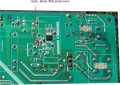
 

R!f@@

Joined Apr 2, 2009
10,004
Finally...
Now comes the tricky part.


Look at the PIC.
First cut off power
Second Discharge the cap.

Now clip the meter negative probe to capacitor negative.
Put the meter in a low VDC range, you going to measure around 1V.
Put the meter positive probe at the gate track of the PCB. FET should be removed.
Now this test is all about how fast you are OK.

We are going to test whether the gate pulse is coming at power up.
If the fet is not there the PWM chip might shut down after a trying.
So you have around 3 second window to take the reading.

So adjust the meter to a appropriate range.
Connect the DMM probes
Keeping you eye on the meter switch on the power.
If the PWM chip is pulsing you will get a low voltage DC, or it even be a negative voltage. It does not matter what polarity you get, I just like to know if there is soft start pulse coming at power up.
 

Attachments

Last edited:

Thread Starter

johndoe45

Joined Jan 30, 2010
364
ok redid first test like twice

with analog meter from beginning it just went from 0 to 5. kept going and going and going way past 3 seconds

test for short circuit???? on board right. not FET itself

on board
ok. analog meter on lowest ohm setting flicks the meter thingy from every pin on board

source and gate showed continuity but drain didn't to any with DMM. copper ring is bad?
 
Last edited:

R!f@@

Joined Apr 2, 2009
10,004
with analog meter from beginning it just went from 0 to 5. kept going and going and going way past 3 seconds
Does the pointer goes like a wind Shield wiper


source and gate showed continuity but drain didn't to any. copper ring is bad?
This test is done on the PCB, if so gate source will give a low resistance reading but not a short circuit.
as for copper ring you have to compromise as you did with the bridge.

Test the FET now. Is the FET OK
 

Thread Starter

johndoe45

Joined Jan 30, 2010
364
yes to windshield wiper question

ok testing. but previous post read analog part

with black on source and red on drain of the actual FET. there is continuity. so FET is shorted?

other way around there isn't continuity
 
Last edited:

R!f@@

Joined Apr 2, 2009
10,004
If the FET is shorted. Drain to Source Reading forward or reversed, will be same.
If Reading is different then FET is OK.
But you need to check
Gate to Source
Gate to Drain
 
Top