Do you know why the same issue is presenting on the new board?
I am trying to determine the root cause, I could try and troubleshoot the board but I imagine I will face the same problems unless i can fix the root cause.
I assume its these small diodes that i should be checking on the board?
and based on the schematic, which diode is the motor BEMF diode?
View attachment 220032
My board is a MC2100ELS-50W. The old board is labeled V1 and my new board is labeled Y2
Hi Max, I checked the diodes, they are all good. i checked DI3, D14, D17.
I get a diode volt reading one way but not the other.
where else should be checking for this short? transistor?
not sure if it is relevant but I get 0 ohm resistance across the + and - of the DC terminals. (no motor attached, board is off the machine) i.e. when i set the multi meter to detect resistance, i get a continuous beep when touching the two terminals.
I don't have a version of that board to compare to the three I have, there are at least 5 versions of this board.
Ensure those diodes are not across the coils of the relays, as you will not get a true reading.
The command you give to start, does it include the ramp angle motor?
Max.
surprisingly, on my old board i get a super high reading 60K ohms.
on my new board i get basically zero between A+ and A-, but there is a definite short(resistance) between the A+ and A- since it beeps on the meter when I use sound.
The first would be the BEMF diode, but you say you checked it as OK.
There is not much else that if shorted , that would show up as shorted M+/M- ?
There is C13 that may give close to that.
Max.
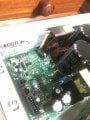
Hi Max, I took a pic of the energy board. I am wondering if the diode that is next to IGBT (both attaches to the heat sink) is the diode you are calling D13. On the board it is D15.
I checked the diode attached to the heat sink and whilst I get OL in ove direction, I only get 0V in the other. This is weird, I also only get 0V when I measure across the IGBT next to it. On my old board I measure 0.4V on the diode and 0.008 on the IGBT.
any help would be much appreciated. I can’t figure out why I have a short between M+ and M-
not sure if i have this right but from the schematic you sent, I see 3 paths to a short where only one component has failed (see pic in previous post)
1. D13 failure
2. C17 failure (assumes the switch at Q2 is locked on or has also shorted)
3. C18 failure (assumes the switch at Q2 is locked on or has also shorted)
i could be way off, but is that logic accurate?
this M+/M- short just doesn't make sense. I get zero resistance.
n.b. there is some flux liquid on the board (alot of it), but the board did work for 30 min before shorting, so not sure if that is at play here.
 Facebook
 Google
 GitHub
 Linkedin