DK30-110 treadmill motor controller speed control

MaxHeadRoom

Joined Jul 18, 2013
30,557
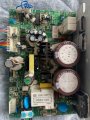
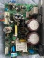
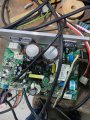
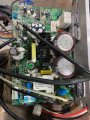
The attached photo is an APS354B treadmill motor controler board that looks similar to the mc2100. Was wondering if the wire colors are the same and if it can be used with the signal generator like the mc2100?
Yes, IIRC it uses the same type of signal, into the same colours in to HD6.
 

Thread Starter

Davrowbf

Joined Feb 15, 2025
69
Yes, IIRC it uses the same type of signal, into the same colours in to HD6.
Thanks Max-HeadRoom appreciate your response. I am sure I will have more questions once I purchase a signal generator. Since I am not a tech person I reaily appreciate a site like this with lots of great reading and very valuable information. Thanks again.
 

Thread Starter

Davrowbf

Joined Feb 15, 2025
69
Yes, IIRC it uses the same type of signal, into the same colours in to HD6.
The connector on this board in the picture has only 7 connections but there are 3 behind it that connects to the selector board that controls the speed and the incline motor and five to the left that connect to the computer board. Using the black, red and blue in the 7 connections do not work with the signal generator that I was using with my mc2100 as a matter of fact I will need to replace my signal generator. I think I may have fried it. (Nothing ventured nothing gained) lol. Would you have a hookup for this board?
 

MaxHeadRoom

Joined Jul 18, 2013
30,557
I do not have it now for that board, but trace the pin that goes to the 4 pin of one of the opto inputs and that will be the PWM and the ground or common usually the BLK wire.
 

Thread Starter

Davrowbf

Joined Feb 15, 2025
69
I do not have it now for that board, but trace the pin that goes to the 4 pin of one of the opto inputs and that will be the PWM and the ground or common usually the BLK wire.
Thanks MaxHeadRoom but your suggestion is beyond my abitity. I'm a Woodworker with limited electronics skills. I was hoping someone here may have a pinout for this board to allow the use of a signal generator.
 

MaxHeadRoom

Joined Jul 18, 2013
30,557
You just need to identify the connector input pin and the input of the 817 opto using the resistance scale of the meter.
There might be a low value resistor in between so it may just read a low (~100Ω) value.
 

Thread Starter

Davrowbf

Joined Feb 15, 2025
69
You just need to identify the connector input pin and the input of the 817 opto using the resistance scale of the meter.
There might be a low value resistor in between so it may just read a low (~100Ω) value.
Pin 1 I assume is the one with the dot? and Pin 4 the one counting c-clockwise 2,3,4? There are 5 of those 817 just infront of the header and two to the right. If pin 4 is just above pin 1 counting c-clockwise I am not getting any reading from that pin on any of those 817? Please forgive my lack of knowledge.
 

MrChips

Joined Oct 2, 2009
34,626
The input is not always at pin-1.
1) You can have a driver that supplies current at pin-1.
2) You can also have a driver that sinks current at pin-2.

If you have 0 volts at both pins 1 and 2 when at idle, then you have case (1)
If you have non-zero volts at both pins 1 and 2 when at idle, then you likely have case (2). It could mean something else.
 

MrChips

Joined Oct 2, 2009
34,626
If your controller is anything looking like this, then yes, positive voltage signal comes in at pin-1 at opto-coupler F817, U1 and U2

Header 2.jpg
 

MaxHeadRoom

Joined Jul 18, 2013
30,557
That is for one of the MC2100 versions, ;)
The thing to watch for when using any kind of 20hz PWM into HD2 pin4, is some may require a series resitor in the input lead as they only have an on-board low resistance, e,g, R2 = 22Ω as shown.
 
Top