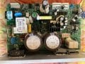
Ok the board has U4A, U5A, U7, U6 and U2 and P4 Header with 7 pins. Pin 1 on U6 & 7 to pin 6 (green) on P4 header reads 220 Kohms. Pin 1 of U2 to pin1 (black) on P4 reads 150 Ohms. Have no idea what all this means
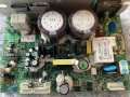
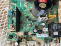
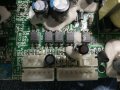
Can you post a full view photo of the board similar to those on post #20 (edit: previous thread was post #426) but at higher resolution?
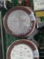
You can also try different sections of the board at different angles so that most of the components are visible and the markings identifiable.
Can you post a full view photo of the board similar to those on post #426 but at higher resolution?
You can also try different sections of the board at different angles so that most of the components are visible and the markings identifiable.
My focus is the be able to control this board with a signal generator or at least without all the componets of the Treadmill. Hope the attached photo is good. Let me know if you need more.
My focus is the be able to control this board with a signal generator or at least without all the componets of the Treadmill. Hope the attached photo is good. Let me know if you need more.
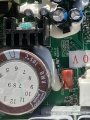
From what I have been reading, you can control the speed by adjusting a trim pot on the board. If this is true then you can replace the trim pot with an external potentiometer. What is the blue trim pot, VR2, at the left bottom corner of your photo? What is its function?
Failing that, the usual method of control is to feed a PWM signal into the control board. Since this board layout is different from the ones we have seen so far, give us some time to research this board.
I have no idea what it's function is but I have a TD-700 V1.2 board here as well and it has three? Are there any pinouts hear for that type of board to use a paulse generator? the wiring look to be the same as the one we are discussing
Studying the board, it does not appear to belong to the same group that includes the MC series, If so then I have no info on those, unfortunately.
It may require delving into the hook up from the console end??
Studing the board, it does not appear to belong to the same group that includes the MC series, If so then I have no info on those, unfortunately.
It may require delving into the hook up from the console end??
Thanks MaxHeadRoom didn't want to cloud the issue just though I'd ask on these board to see if any of the learned people on here knew of them. Sure would appreciate a work around for the board we have been discussing though it would run my Bandsaw or Drill Press quite nicely
This controller (DCMD67) does not accept PWM input. See the YouTube video below.
S+ and S- are 0 to 5V input logic signals that will step up or down the motor speed.
(Edit: ST, S+ and S- are connected to the cathodes on the opto-couplers. Pull ST to GND to energize a relay. Temporarily pull S+ and S- to GND to speed up and speed down.)
At 24:20 he inputs +5 VDC to pin-6. (Check your board first to see if you already have +5 VDC on board.)
He connects pin-5 to GND via a toggle switch in order to energize a power relay.
You can use a 110 V 50 W incandescent lamp in lieu of the motor for testing.
I got this information from this YouTube video, 33 minutes (in Spanish).
Still hoping some great tech out there will produce a simple drawing to connect my TM motor control board to a signal generator similar to the mc 2100. Oh don't I wish I had the knowledge to undersand the working of these boards. In the menntime I truly appreciate the experience and knowledge I have gained on here the last couple day. Thanks again guys I will continue to follow this great fourm
Still hoping some great tech out there will produce a simple drawing to connect my TM motor control board to a signal generator similar to the mc 2100. Oh don't I wish I had the knowledge to undersand the working of these boards. In the menntime I truly appreciate the experience and knowledge I have gained on here the last couple day. Thanks again guys I will continue to follow this great fourm
 Facebook
 Google
 GitHub
 Linkedin
 605.5 KB Views: 13
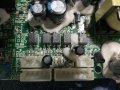 610.6 KB Views: 13