Facebook
 Google
 GitHub
 Linkedin

Hi guys! Sorry for the huge delay, but Ifiinally got some time to take some measurements and here are the results.
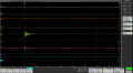
This is how the system looks at no load. Quite stable.
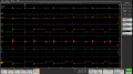 Here I have the load increased to around 0.9A. It is still stable at 5V. (i also added the voltage across the inductor)
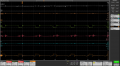 As you can see. As soon as I increase the current over 1A the voltage starts dropping. So does the feedback voltage. I will add more pictures both zoomed in and out but these are the most relevant.
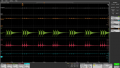
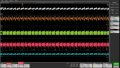
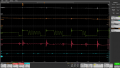

I tried once again to pinpoint the issue but I just cannot get to it. Any ideas?
This is how the system looks at no load. Quite stable.
Here I have the load increased to around 0.9A. It is still stable at 5V. (i also added the voltage across the inductor)As you can see. As soon as I increase the current over 1A the voltage starts dropping. So does the feedback voltage. I will add more pictures both zoomed in and out but these are the most relevant.I tried once again to pinpoint the issue but I just cannot get to it. Any ideas?