Facebook
 Google
 GitHub
 Linkedin

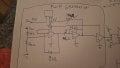
I made a boost converter and it works as expected. The problem is the logical PWM generation and gate driver require a separate battery supply. The boost converter power stage is powered by a DC 10 volt supply. I want to power the logic and power stage with the DC supply but when i connect it the voltage of the PWM logic circuit drops at boost converter startup causing OCP of DC power supply to trip. I don't know if the inrush current causes the voltage to suddenly drop but it all works well with two separate supplies.
Gate driver: TC4420CPA
MOSFET: STP40NF10L
Diode: MBR30H100CTG
Voltage regulator for PWM stage: L7806
PI regulator and PWM generation is made with TL071CP
PWM stage is comprised of a schmitt trigger, integrator and comparator. The comparator compares the outputed triangle wave of the integrator with the output of the PI regulator to create a variable duty cycle going to the gate driver.
Comparator used is: LM311N
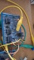
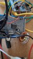
EDIT: Forgot to add that there is a decoupling 10uF cap at gate driver Vcc and GND and a decoupling cap at voltage reg Vcc and GND
Mod: Cleaned up you circuit drawing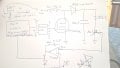
Gate driver: TC4420CPA
MOSFET: STP40NF10L
Diode: MBR30H100CTG
Voltage regulator for PWM stage: L7806
PI regulator and PWM generation is made with TL071CP
PWM stage is comprised of a schmitt trigger, integrator and comparator. The comparator compares the outputed triangle wave of the integrator with the output of the PI regulator to create a variable duty cycle going to the gate driver.
Comparator used is: LM311N
EDIT: Forgot to add that there is a decoupling 10uF cap at gate driver Vcc and GND and a decoupling cap at voltage reg Vcc and GND
Mod: Cleaned up you circuit drawing
Attachments
-
 1.4 MB Views: 1
Last edited by a moderator: