Problem with powering DIY boost converter

Thread Starter

deadlyhazzard

Joined Mar 22, 2023
4
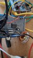
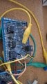
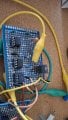
I made a boost converter and it works as expected. The problem is the logical PWM generation and gate driver require a separate battery supply. The boost converter power stage is powered by a DC 10 volt supply. I want to power the logic and power stage with the DC supply but when i connect it the voltage of the PWM logic circuit drops at boost converter startup causing OCP of DC power supply to trip. I don't know if the inrush current causes the voltage to suddenly drop but it all works well with two separate supplies.
Gate driver: TC4420CPA
MOSFET: STP40NF10L
Diode: MBR30H100CTG
Voltage regulator for PWM stage: L7806
PI regulator and PWM generation is made with TL071CP
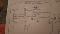
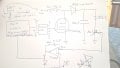
PWM stage is comprised of a schmitt trigger, integrator and comparator. The comparator compares the outputed triangle wave of the integrator with the output of the PI regulator to create a variable duty cycle going to the gate driver.
Comparator used is: LM311N
1000012448.jpg

1000012449.jpg

EDIT: Forgot to add that there is a decoupling 10uF cap at gate driver Vcc and GND and a decoupling cap at voltage reg Vcc and GND

Mod: Cleaned up you circuit drawing1000012450.jpg
 

Attachments

Last edited by a moderator:
I think you want to know how to make the "PWM stage is comprised of a Schmitt trigger, integrator and comparator" to run with an unregulated 10V supply, but you do not show us a schematic of the PWM stage.
 
Last edited:

Ian0

Joined Aug 7, 2020
13,201
Is there a reason why you didn’t use a UC3842 or something similar?Judging by your circuit, you are attempting a voltage-mode regulator with no current limit. There’s a reason that most switched-mode controllers use current-mode control. . . .
 

Ian0

Joined Aug 7, 2020
13,201
My PWM stage is made as follows
View attachment 369984

I did not use a PWM IC because i wanted to make it myself
Ok. No reason why you should t be able to make it work, even with voltage-mode control.
Where do the unlabelled non-inverting inputs go?
which are op-amps and which are comparators?
Do your comparators have open-collector or push-pull outputs? (part number?)
where does the output of the error amplifier (from your previous diagram) connect to this diagram?
what frequency is your triangle-wave?
 

Thread Starter

deadlyhazzard

Joined Mar 22, 2023
4
Ok. No reason why you should t be able to make it work, even with voltage-mode control.
Where do the unlabelled non-inverting inputs go?
which are op-amps and which are comparators?
Do your comparators have open-collector or push-pull outputs? (part number?)
where does the output of the error amplifier (from your previous diagram) connect to this diagram?
what frequency is your triangle-wave?
Ok. First two are TL071cp ip amps. Last one is a LM311N comparator. The non inverting input of second op amp goes to same voltage divider as inverting input of first op amp. Non inverting input of comparator goes to output of PI regulator of feedback loop. LM311N has a 1kohm pull up resistor i forgot to add in the schematic. Frequency of triangle wave is 100khz.

The circuit works if i use a separate battery supply for the gate driver and PWM control and a dc supply for the power stage. When i start tje circuit with the same dc supply for both the power stage and control stage the voltage collapses causing the switching to stop and high inrush current is drawn
 

Ian0

Joined Aug 7, 2020
13,201
Why did you use a TL071? some varieties need a minimum power supply of 10V, and it doesn’t like inputs too close to the power supply voltages
it also has a nasty little quirk of changing phase when the inputs are driven too close to the negative supply, and I suspect that is what happens when the output starts to load the power supply.

You have a 6V power supply, find a rail-to-rail op amp that works on 6V and try again.
 

Thread Starter

deadlyhazzard

Joined Mar 22, 2023
4
Why did you use a TL071? some varieties need a minimum power supply of 10V, and it doesn’t like inputs too close to the power supply voltages
it also has a nasty little quirk of changing phase when the inputs are driven too close to the negative supply, and I suspect that is what happens when the output starts to load the power supply.

You have a 6V power supply, find a rail-to-rail op amp that works on 6V and try again.
It works though even with load. It just doesnt work with single supply i dont see how that has anything to do with the used tl071cp
 
Top